

Part of the JCB Repair Manuals.
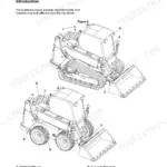
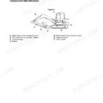
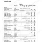
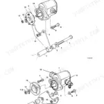
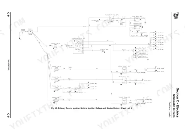
All 622 pages of this JCB Midi CX Backhoe Loader Service Manual PDF (OEM #9803/9400-08) focus on one thing: getting your machine out of the bay and back on the dirt. Inside, you get complete hydraulic schematics for the main pump and loader circuits, plus high-resolution wiring diagrams to trace out stubborn electrical faults. Open to the troubleshooting section to diagnose complex transmission issues, or follow the detailed procedures to rebuild the engine cooling pack step-by-step. Verify the flow compensator valve standby pressure is holding steady at 31 bar, then double-check the front and rear wheel nuts are locked down to 680 Nm before returning the equipment to service. Dealership labor rates will eat your profit margins alive. Grab this bookmarked file, pull it up on your shop tablet, and fix the iron yourself.
What's Inside This Manual
| System | Pages | Key Topics |
|---|---|---|
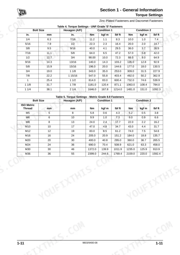
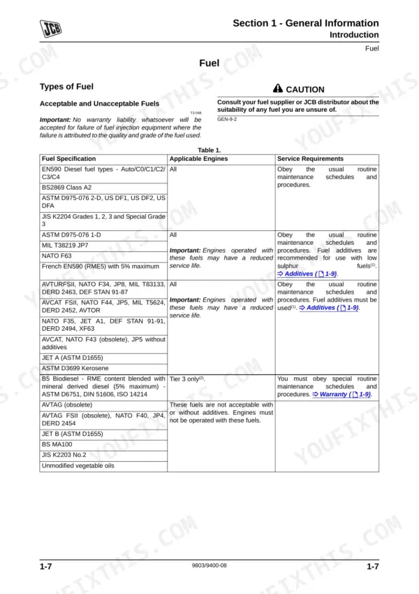
| General Information | 1-28 | Introduction, Identifying the Machine, Fuel, Torque Settings, Hydraulic Connections, Service Tools, Service Aids, Terms and Definitions |
| Care and Safety | 29-44 | Safety Notices, Safety Check List, Operating Safety, Maintenance Safety, Safety Labels |
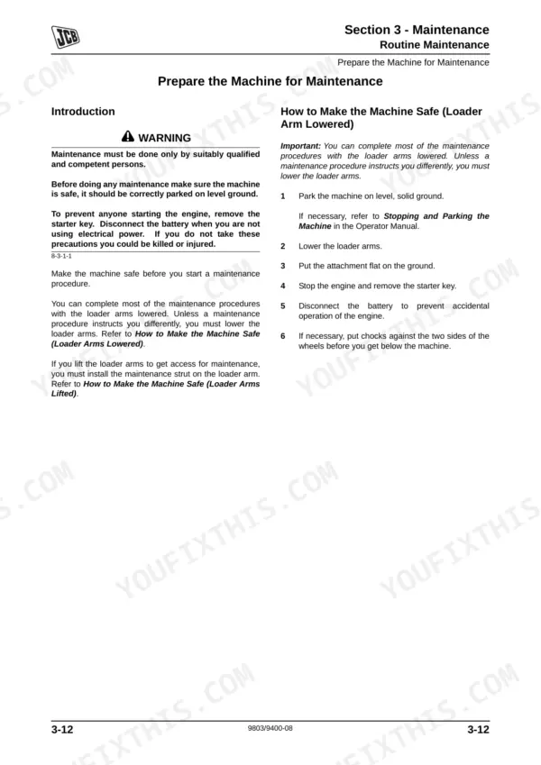
| Maintenance | 45-104 | Routine Maintenance, Service Schedules, Functional Test and Final Inspection, Fluids, Lubricants and Capacities, Prepare the Machine for Maintenance, Cleaning the Machine |
| Attachments | 105-112 | Service Procedures |
| Body and Framework | 113-218 | Service Tools, Rivet Nuts, Slide Hammer Kit, Cab Air Conditioning System, Cab, Air Conditioning Condenser, Cab HVAC Unit, Cab Seat |
| Electrics | 219-310 | Service Tools, Technical Data, Schematic Circuits, Service Procedures, Harness Data |
| Controls | 311-326 | Service Tools, Steering Column, Column Switches, Control Rods and Linkages, Control Cables, Anti-Spill Mechanism |
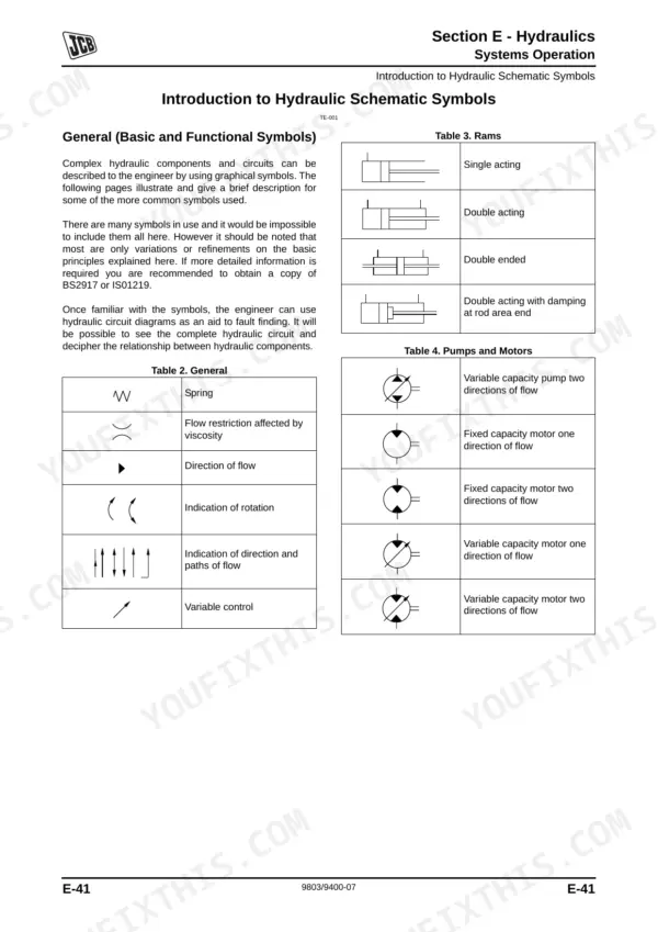
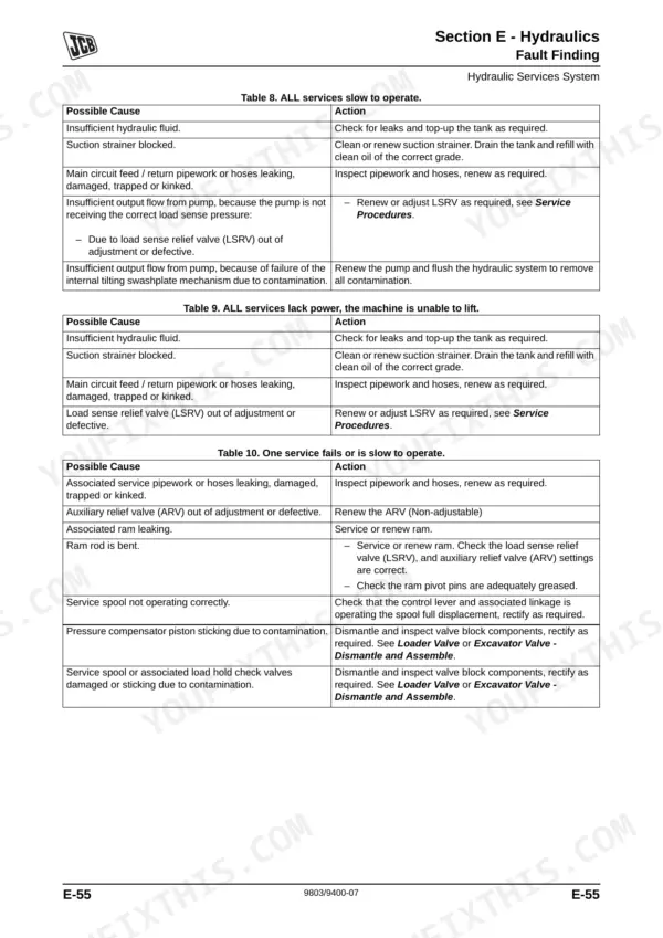
| Hydraulics | 327-478 | Service Tools, Technical Data, Systems Operation, Introduction to Hydraulic Schematic Symbols, Schematic Circuits, Fault Finding, Service Procedures, Hydraulic Services Pump |
| Transmission | 479-548 | Service Tools, Technical Data, Moving a Disabled Machine, Systems Operation, Schematic Circuit, Service Procedures, Fault Finding, Transmission Pump |
| Brakes | 549-580 | Service Tools, Technical Data, Systems Operation, Fault Finding, Service Procedures, Compensating Master Cylinder, Service Brakes, Park Brake |
| Steering | 581-610 | Service Tools, Technical Data, Systems Operation, Fault Finding, Service Procedures, Priority Valve, Power Track Rod, Link Arms |
| Engine | 611-622 | Technical Data, Engine Cooling Pack, Removal and Replacement |
Quick Reference Specifications
| Specification | Value | Page |
|---|---|---|
| Flow Compensator Valve (Standby pressure) | 31 bar (31.6 kgf/cm2, 450 lbf/in2) | p. 339 |
| Standby pressure | 31 bar (31.6 kgf/cm2, 450 lbf/in2) | p. 400 |
| Creep Valve Weight | 0.7 kg (1.5 lbs) | p. 497 |
| ROPS/FOPS Mounting Bolts Torque | 205 Nm | p. 68 |
| Front/Rear Wheel Nuts Torque | 680 Nm | p. 101 |
| AC Refrigerant Quantity | 1.2 Kg | p. 126 |
| AC High Pressure Switch Setting | 27.5 bar | p. 126 |
| Hydraulic Services Pump Pressure Cut-Off Valve Setting | 265 bar | p. 339 |
| Hydraulic Steer Unit Relief Valve Operating Pressure | 125 bar | p. 586 |
| Engine Idle Speed | 1200 r.p.m. | p. 616 |