
Part of the John Deere Repair Manuals.
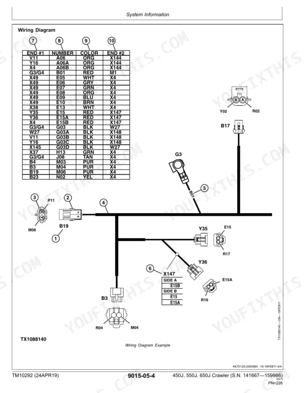
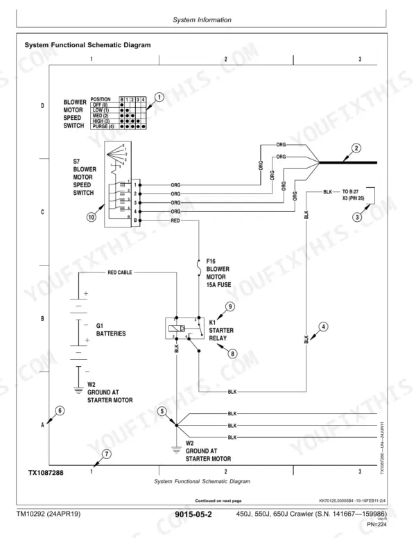
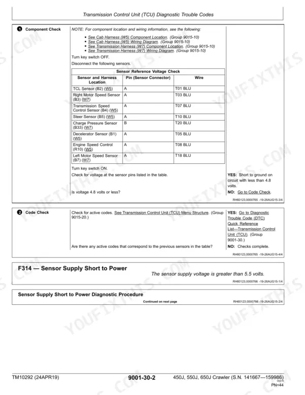
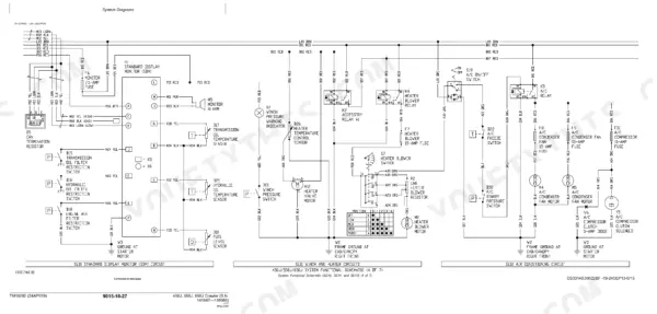
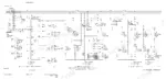
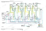
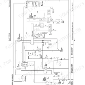
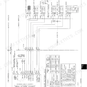
Running a 450J, 550J or 650J crawler dozer on a repair job puts you in TM10292, the John Deere 450J, 550J, 650J operation and test manual PDF, 714 pages of factory diagnostic and test data written for all three J-Series tractors. Diagnostic trouble codes open the book, walking the standard display monitor, electrohydraulic controller and blade joystick faults one code at a time. System diagrams and wiring schematics fill the electrical chapter, the longest in the book, tracing harness runs and connector pins the way the factory drew them, while hydraulic and hydrostatic theory, tests and adjustments close out the volume. Check the fuel level sender against 168 to 192 ohms at a full tank, or read transmission oil temperature at 3.3 to 3.8 kohms at 20 C (68 F). At two in the morning there is nobody to call. Bookmarked and text-searchable, yours to keep for as long as you own the machine.
What's Inside This John Deere 450J, 550J, 650J Manual
| System | Pages | Key Topics |
|---|---|---|
| General Information | 7-18 | Safety (Recognize Safety Information, Follow Safety Instructions, Operate Only If Qualified) |
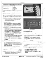
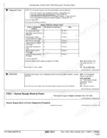
| Diagnostic Trouble Codes | 19-186 | Standard Display Monitor Diagnostic Trouble Codes, Electrohydraulic Controller Diagnostic Trouble Codes, Blade Control Joystick Diagnostic Trouble Codes |
| Operational Checkout Procedure | 187-202 | System Operational Checks |
| Engine | 203-220 | Theory of Operation, System Diagnostic Information |
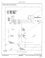
| Electrical System | 221-500 | System Diagrams |
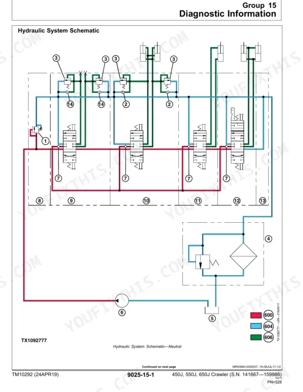
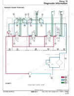
| Hydraulic System | 501-580 | Theory of Operation, Diagnostic Information, Adjustments, Tests |
| Hydrostatic System | 581-688 | Theory of Operation, Diagnostic Information, Tests |
| Heating and Air Conditioning | 689-714 | Theory of Operation, Diagnostic Information, Test |
Quick Reference Specifications
| Specification | Value | Page |
|---|---|---|
| Fuel Level Sensor (B10) Resistance | 168—192 ohms at 100% Fill (full), 129.5—150.5 ohms at 75% Fill, 96—114 ohms at 50% Fill, 67.5—82.5 ohms at 25% Fill, 4—16 ohms at 0% Fill (empty) | p. 27 |
| Transmission Oil Temperature Sensor (B17) Resistance | 90—108 kohms at -40°C (-40°F), 26—31 kohms at -20°C (-4°F), 8.7—10.2 kohms at 0°C (32°F), 3.3—3.8 kohms at 20°C (68°F), 1.4—1.6 kohms at 40°C (104°F), 648—708 ohms at 60°C (140°F), 317—350 ohms at 80°C (176°F), 170—186 ohms at 100°C (212°F), 97—105 ohms at 120°C (248°F) | p. 31 |
| Engine Speed Control Switch (R10) Resistance Between Pins A and C | 980—1020 ohms | p. 122 |
| Loaded Rotary-Type Pump Rated Pressure | 6.9 kPa, 0.069 bar, 1.0 psi | p. 215 |
| Fuel Level Sensor Resistance (100% Fill) | 168—192 ohms | p. 27 |
| Fuel Level Sensor Resistance (0% Fill) | 4—16 ohms | p. 27 |
| Transmission Oil Temperature Sensor Resistance (100°C) | 170—186 ohms | p. 31 |
| Pump Pressure Control Pilot (PCP) Rear Resistance | 20.7—25.3 ohm | p. 75 |
| Right Motor Shift Solenoid Resistance (20°C) | 6.9—12.7 ohms | p. 101 |
| Engine Slow Idle Speed | 875—925 rpm | p. 196 |
| Engine Fast Idle Speed | 2330—2360 rpm | p. 196 |
| Blade Raise Cycle Time (Typical New) | 2.4 seconds | p. 201 |
John Deere 450J, 550J, 650J Common Problems This Manual Covers
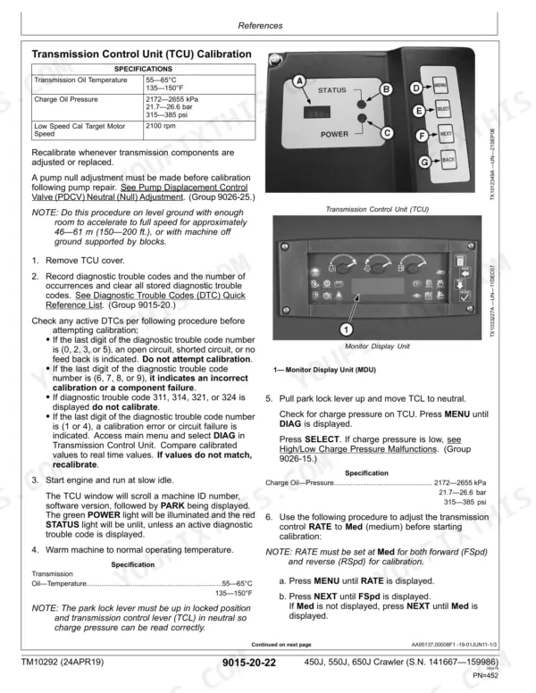
John Deere 450J will not move, no hydrostatic drive response, dash throws TCU communication codes
Check the TCU diagnostic trouble codes starting before pulling anything apart. Verify the park lock lever and neutral start circuit first: measure the engine speed control switch (R10) between pins A and C on page 122, looking for 980 to 1020 ohms. Out of range, replace the switch.
Manual Section: Transmission Control Unit (TCU) Diagnostic Trouble CodesTransmission oil temperature alarm and power derate during heavy dozing on hot days
Drain and check oil level cold before condemning the sensor. Clean the cooler core, then back-probe the transmission oil temperature sensor (B17) and compare resistance to the chart on page 31: 170 to 186 ohms at 100 degrees C, 317 to 350 ohms at 80 degrees C. Readings way off mean a bad sensor, not real overtemp.
Manual Section: Diagnostic Trouble Codes (SDM) p. 31Weak or slow blade response, hydraulic filter restricted warning on the monitor
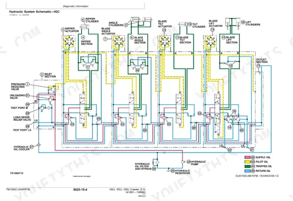
Replace the hydraulic oil filter and top off the reservoir first, since restriction warnings are usually plugged media. Then run the blade raise cycle time check on page 201 at fast idle. A new machine lifts in 2.4 seconds; anything dragging well past that points to pump wear. Trace the circuit on the schematic.
Manual Section: Hydraulic System Malfunctions p. 201Hard starting and rough running after startup until the engine warms up
Change both fuel filters and bleed the system completely before chasing injectors. Verify fuel supply pressure against the loaded rotary pump rating on page 215 at 6.9 kPa (1.0 psi). Then confirm engine speeds in the operational checkout: slow idle 875 to 925 rpm, fast idle 2330 to 2360 rpm on page 196.
Manual Section: Engine Malfunctions p. 215Blade drifts or joystick control cuts out intermittently, X-axis sensor fault on the display
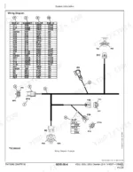
Inspect the joystick harness connector for backed-out pins and green corrosion before ordering a sensor assembly. Work the Blade Control Joystick codes in the section covering X-axis sensor, internal, and setup failures, then rerun joystick calibration. Confirm the fix with the blade raise cycle time of 2.4 seconds listed on page 201.
Manual Section: Blade Control Joystick (BCJ) Diagnostic Trouble CodesMachine tracks in one direction only, will not reach full ground speed under load
Test brake release pressure first; the multi-function valve on page 657 should release between 1379 and 2758 kPa, and a dragging brake mimics a bad motor. Measure the right motor shift solenoid at 6.9 to 12.7 ohms at 20 degrees C per page 101. Torque the multi-function valve lock nut to 79 N.m on reassembly.
Manual Section: Hydrostatic System Malfunctions p. 657Frequently Asked Questions
What are the transmission oil filter replacement specs for a John Deere 450J, 550J, 650J crawler dozer?
If the transmission oil filter restriction light is on, the transmission oil filter should be replaced. Refer to the 'Change Transmission Oil and Filter' procedure in the Operator's Manual for detailed instructions. p. 39
What is the torque spec for the engine speed control nut on a John Deere 450J, 550J, 650J crawler dozer?
The torque specification for the engine speed control nut is 2.7 N·m (24 lb.-in.). p. 486
What is the fuel level sensor resistance specification on a John Deere 450J, 550J, 650J crawler dozer?
The fuel level sensor resistance is 168—192 ohms at 100% fill, 129.5—150.5 ohms at 75% fill, 96—114 ohms at 50% fill, 67.5—82.5 ohms at 25% fill, and 4—16 ohms at 0% fill (empty). p. 27
What is the park brake solenoid resistance spec on a John Deere 450J, 550J, 650J crawler dozer?
The resistance for the park brake solenoid (Y11) is 6—8 ohms. p. 79
Is this John Deere 450J Technical Manual a digital download?
One searchable PDF covering 714 pages, delivered instantly. No disc, no shipping, no waiting on the post.
Am I able to print pages from this manual?
Yes. Print a chapter or just the pages for the job at hand, for use in your own shop. Any home or office printer works.







Reviews
There are no reviews yet.