
Part of the John Deere Repair Manuals.
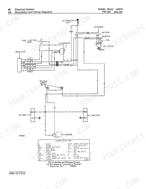
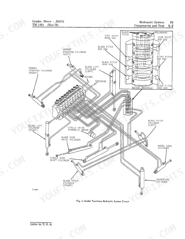
All 526 pages of this John Deere JD570 Technical Manual PDF (OEM #TM-1001) cover the 570 and 570A Motor Graders across their full production run from 1967 to 1987. Inside: complete wiring diagrams for the charging system, starting motor, and electrical circuits, plus hydraulic schematics tracing fluid routing through power steering, brakes, and the main hydraulic system. You get a full troubleshooting section for the Power Shift transmission, page after page of exploded views across all major systems, and torque specifications built into every Power Train procedure. Set your transmission pump to 175 ± 10 psi with the filter relief valve blocked; Differential Control Valve pressure reads 420–480 psi at 2300 rpm on the 570 or 635 ± 25 psi at 2450 rpm on the 570A. Your grader is down. Get factory numbers, not forum guesses. Bookmarked and keyword-searchable; pull it up on your tablet and start wrenching.
What's Inside This John Deere JD570, JD570A Manual
| System | Pages | Key Topics |
|---|---|---|
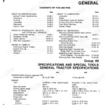
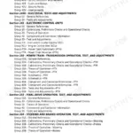
| General | 5-64 | Machine Specifications, Predelivery Services, Tune-Up & Adjustment, Lubrication Chart, Component Separation, Special Tools |
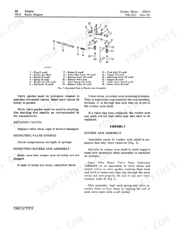
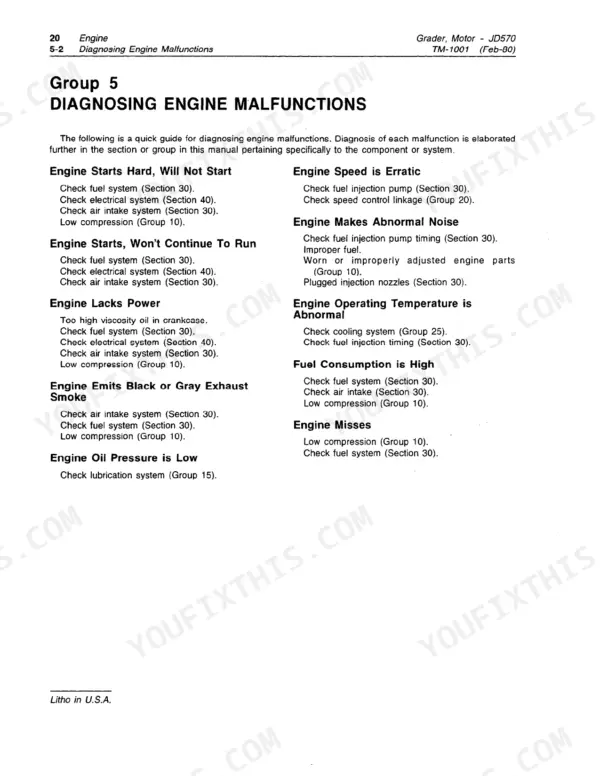
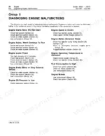
| Engine | 65-102 | Engine Malfunctions, Basic Engine Repair, Valve Tappet Clearance, Lubrication System, Speed Control Linkage, Cooling System |
| Fuel System | 103-128 | Fuel System Malfunctions, Fuel Tank & Filters, Air Intake System, Turbocharger Diagnosis, Fuel Injection Pump, System Specifications |
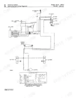
| Electrical System | 129-206 | Wiring Diagrams, Charging System Tests, Alternator Repair, Starting Motor Diagnosis, Battery Tests, Miscellaneous Components |
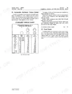
| Power Train | 207-372 | Engine Disconnect Clutch, Transfer Drive Repair, Power Shift Transmission Operation, Differential Control, Final Drive System, Torque Specifications |
| Power Steering and Brakes | 373-406 | Power Steering Valve Diagnosis, Brake Valve Malfunctions, Brake Cylinders & Disks, Parking Brake Adjustment, Hydraulic System Flow |
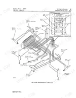
| Hydraulic System | 407-502 | System Components & Tests, Analyzer Testing, Filters & Accumulators, Main Hydraulic Pump, Function Control Valves, Hydraulic Cylinders, Circle Drive Motor, Saddle Valve |
| Miscellaneous | 503-524 | Circle Drive Gearbox, Drawbar & Moldboard Adjustment, Saddle & Main Frame, Front Axle & Scarifier, Specifications & Special Tools |
Quick Reference Specifications
| Specification | Value | Page |
|---|---|---|
| All Models | ||
| Cable threads in yokes clearance | 1/4-inch | p. 326 |
| Transmission pump pressure (with filter relief valve blocked) | 175 ± 10 psi (12 ± 0.68 bar) | p. 495 |
| Transmission pump minimum flow (with filter relief valve blocked) | 11 gpm | p. 491 |
| Blade Lift Drift Specification | 0.06 in. (1.5 mm) maximum in 15 minutes | p. 436 |
| Hydraulic System Pressure | 2000 psi | p. 6 |
| Tire pressure (13.00-24, 8-ply) | 25 psi | p. 21 |
| Wheel retaining cap screws torque | 300 lb-ft | p. 27 |
| Engine oil pressure (at 2300 rpm) | 40 to 60 psi | p. 45 |
| JD570 | ||
| Differential Control Valve pressure, JD570 | 420 to 480 psi at 2300 rpm | p. 492 |
| JD570-A | ||
| Differential Control Valve pressure, JD570-A | 635 ± 25 psi at 2450 rpm | p. 492 |
| Net engine flywheel power | 85 hp | p. 6 |
| Engine lubrication, including filter | 3 gal. | p. 491 |
John Deere JD570, JD570A Common Problems This Manual Covers
Blade drifts or creeps with all control valves in neutral, closed-center hydraulic system
Measure blade lift drift directly at the cylinder; the limit is 0.06 in. (1.5 mm) maximum in 15 minutes (page 436). If drift exceeds spec, test main hydraulic pump standby pressure at 2300 to 2400 psi (page 491), then trace internal leakage in the function control valve and cylinder seals using the hydraulic schematic.
Manual Section: Hydraulic System Malfunctions p. 407Engine oil pressure light on or gauge reads below normal at operating temperature
Verify oil level and inspect for contamination before starting the engine. Oil pressure at 2300 rpm must read 40 to 60 psi (page 45); below 40 psi at operating temperature points to worn bearings or a failing oil pump. Check for external leaks at the filter base and drain plug. Follow engine lubrication malfunction procedures starting at page 65.
Manual Section: Engine Lubrication System Malfunctions p. 65Power steering requires excessive effort or front wheels wander and won't hold a straight line
Inspect the power steering valve spool and centering springs for debris or wear per the hydraulic schematic. Check hydraulic system pressure; the main circuit must hold 2000 psi (page 6). If the unit steers with no wheel input, remove and flush the spool bore before reassembling. Follow the power steering valve malfunction guide at page 373.
Manual Section: Power Steering Valve Malfunctions p. 373Frequently Asked Questions
What are torque specs for blade mounting bolts on John Deere JD570A?
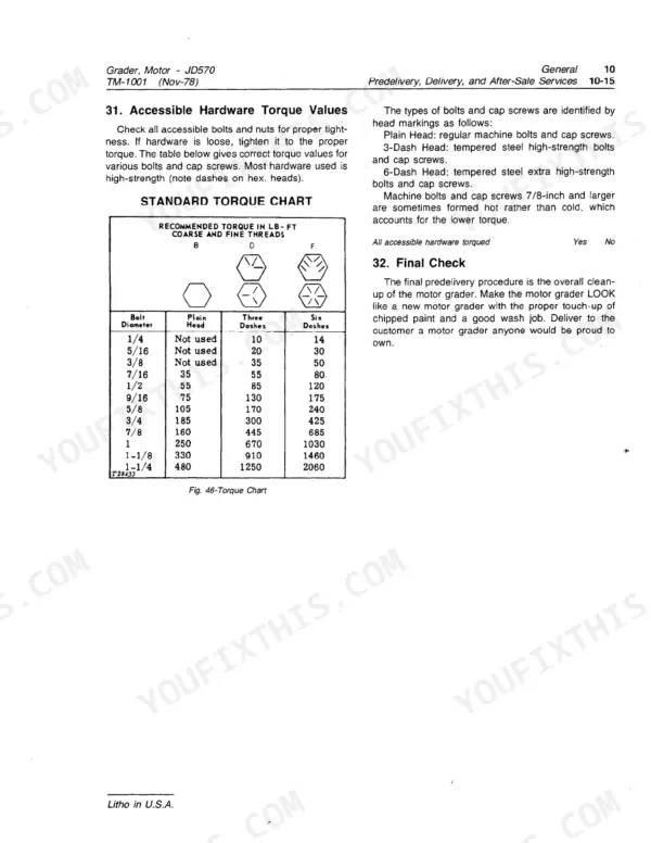
For moldboard extension installation, the hardware (including blade mounting bolts) should be tightened to 170 ft-lbs. The cap screw used to stabilize the moldboard extension should be tightened to 105 ft-lbs. p. 511
How do you fix john Deere JD570 motor grader engine runs rough at idle, normal only when injection pump bleeder is open?
Check the fuel system for air ingress using the troubleshooting chart on page 103. Inspect all fuel line fittings, filter housings, and the lift pump for suction-side leaks. If air returns after bleeding, remove and pressure-test the injection pump seals. Fast idle must stabilize at 2450 ± 50 rpm (page 96) after repairs. p. 103
How do you fix blade drifts or creeps with all control valves in neutral, closed-center hydraulic system?
Measure blade lift drift directly at the cylinder; the limit is 0.06 in. (1.5 mm) maximum in 15 minutes (page 436). If drift exceeds spec, test main hydraulic pump standby pressure at 2300 to 2400 psi (page 491), then trace internal leakage in the function control valve and cylinder seals using the hydraulic circuit diagram. p. 407
How do you fix direction selection lever moves freely but transmission cable doesn't respond, no forward or reverse?
Inspect the transmission end cable at both yokes for disconnection or misalignment. Verify cable threads are seated correctly in both yokes with 1/4-inch minimum clearance (page 326). Adjust the cable end to remove slack, then test each forward and reverse speed for positive engagement. Replace worn linkage pins or a kinked cable housing before adjusting. p. 207
What format is this manual in?
This is a 526-page searchable PDF ready for immediate download. Works on any device, so pull it up on your phone while you're under the hood. No shipping, no waiting.
Is this John Deere JD570 manual print-friendly?
Yes. Print individual pages or full chapters for your own shop use, on letter or A4 paper.
Are wiring diagrams part of this John Deere JD570 Technical Manual?
A wiring diagram for the John Deere JD570, JD570A electrical system is included.






Reviews
There are no reviews yet.