
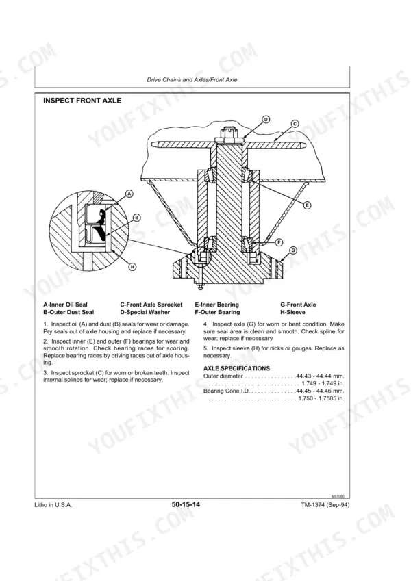
Part of the John Deere Repair Manuals.
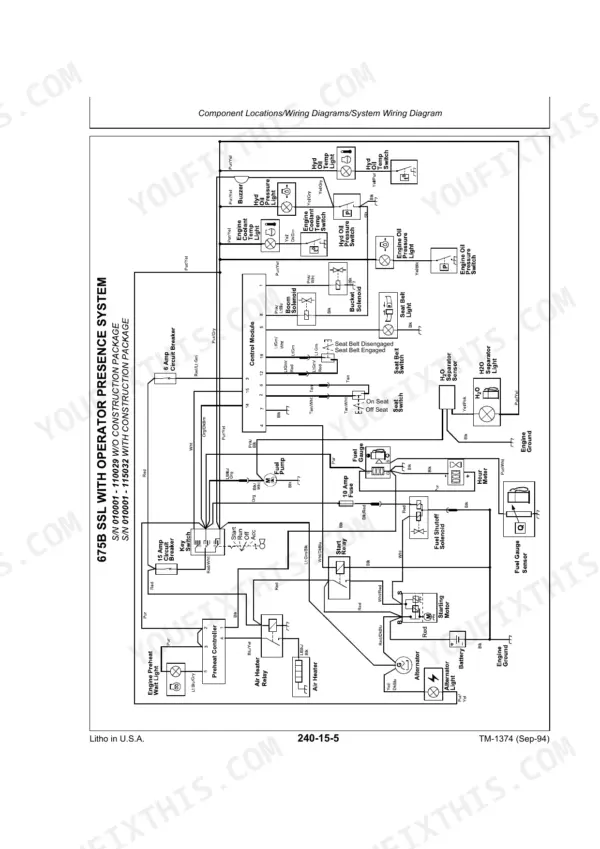
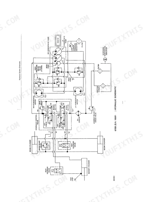
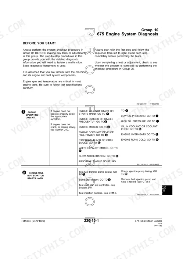
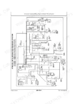
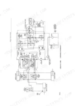
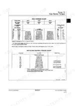
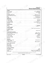
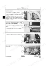
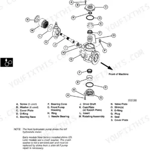
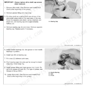
This 267-page John Deere 675 Technical Manual (OEM #TM1374) covers every system on the 675 and 675B Skid Steer Loaders, from engine and power train to electrical and hydraulics. Open it up and you get wiring diagrams for chasing electrical faults, hydraulic schematics for the charge pump and main control valve, and a full torque chart with metric hardware specs so you're not guessing on fasteners. You also get dedicated operation and test sections: system relief valve pressure tests, hydraulic pump flow tests, and boom raise cycle time checks, plus power train and electrical diagnosis procedures. Set your relief valve pressures using the exact factory checkout values in Groups 05 and 10, not a shop-manual approximation. Your loader won't fix itself while you flip through a photocopy. Every section is bookmarked and searchable, so you jump straight from the TOC to the wiring diagram or torque spec you need and get back under the machine.
What's Inside This John Deere 675, 675B Manual
| System | Pages | Key Topics |
|---|---|---|
| 675 and 675B | 1-6 | |
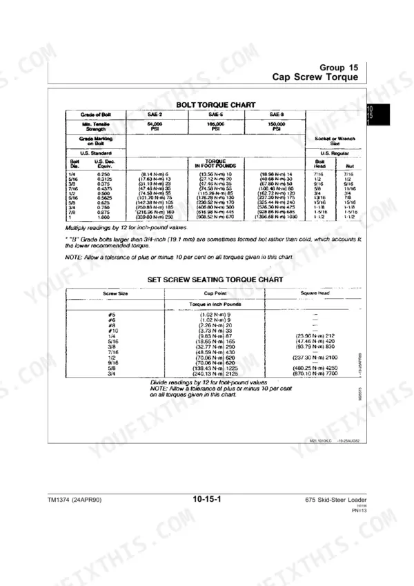
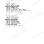
| General Information | 7-28 | Introduction and Safety (Loader Specifications, Bucket Specifications), Cap Screw Torque (Bolt Torque Chart, Metric Hardware Torque Specifications), Tune-Up (Skid-Steer Loader) |
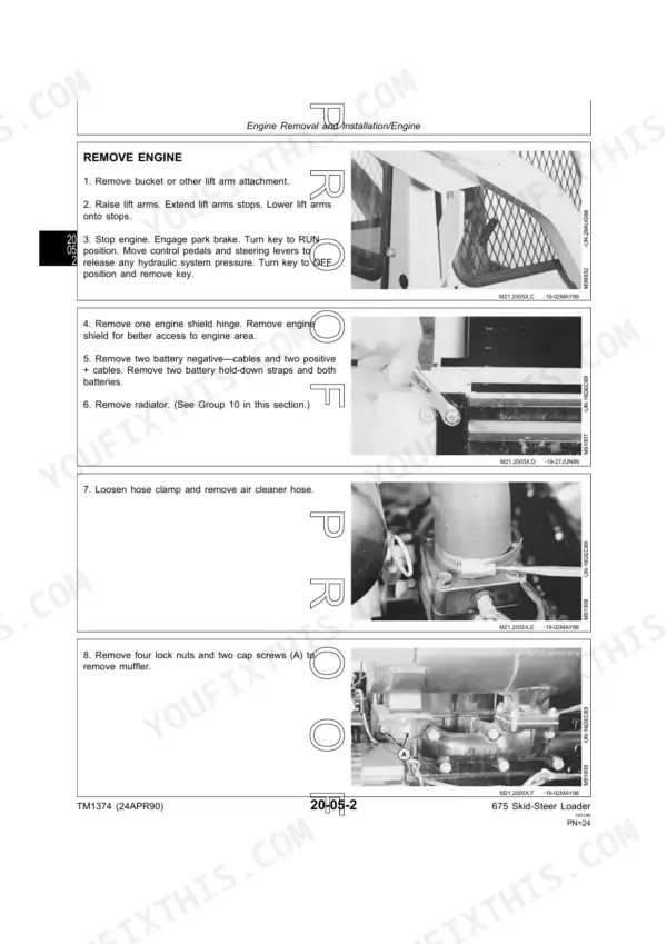
| Engine | 29-42 | Engine Removal and Installation, Cooling System |
| Fuel and Air System | 43-54 | Throttle Control Linkage, External Fuel Supply |
| Electrical | 55-58 | Seat Lockout Switch, Service Equipment and Tools, Adjust Seat Lockout Switch, Replace Deluxe Seat Switches |
| Power Train | 59-136 | Hydrostatic Pumps, Hydrostatic Motor, Drive Chains and Axles, Drive Shaft |
| Steering and Brakes | 137-146 | Park Brake, Steering Neutralizer |
| Hydraulics | 147-191 | Hydraulic Charge Pump, Main Control Valve, Auxiliary Control Valves, Hydraulic Cylinders, Oil Cooler, Miscellaneous Hydraulics |
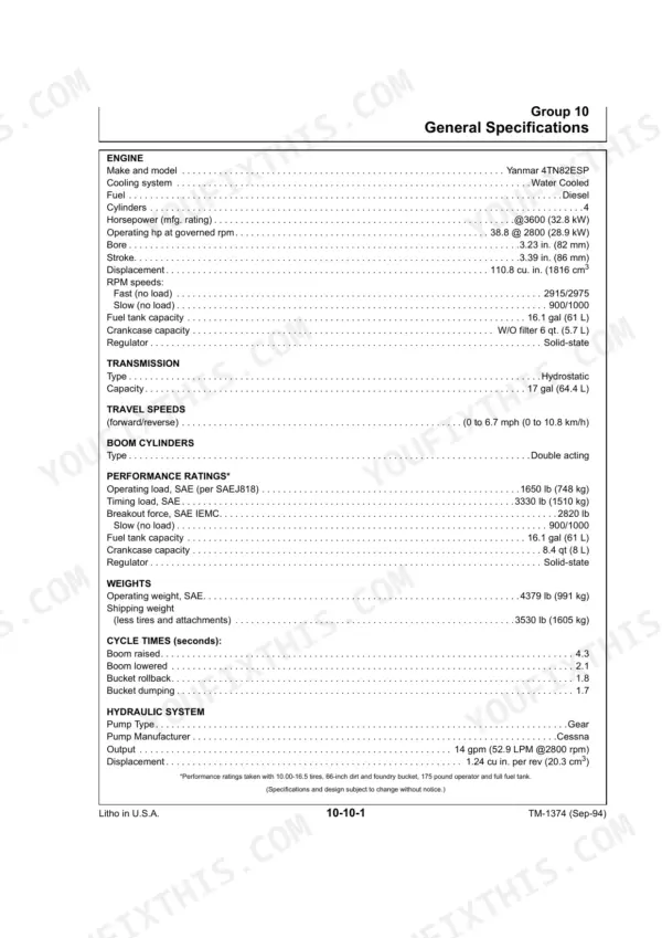
| Specifications/Operational Checkout Procedure | 192-199 | Specifications, Operational Checkout Procedure |
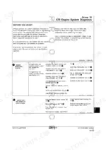
| Engine/Fuel System Operation and Tests | 200-213 | Engine and Fuel System Checkout, Engine and Fuel System Diagnosis, Component Tests and Adjustments |
| Electrical Operation and Tests | 214-241 | Electrical System Checkout, Electrical System Diagnosis, Component Locations/Wiring Diagrams |
| Power Train Operation and Tests | 242-257 | Power Train System Checkout, Power Train System Diagnosis |
| Hydraulic Operation and Tests | 258-267 | System Relief Valve Pressure Test, Boom Circuit Relief Valve Pressure Test, Hydraulic Pump Flow Test, Boom Raise Cycle Time Test |
Quick Reference Specifications
| Specification | Value | Page |
|---|---|---|
| Hydraulic System Checkout | Group 05 | p. 3 |
| Hydraulic Charge Pump | Group 05 | p. 3 |
| Hydraulic System Diagnosis | Group 10 | p. 3 |
| Drive Chains and Axles | Group 15 | p. 3 |
| Seal Repair Kit | available through your parts catalog | p. 86 |
| Final Drive Chain Slack | 6 mm (1/4 in.) | p. 107 |
| Torque for cap screws (A) on hydraulic charge pump | 37-42 N·m (27-31 lb-ft) | p. 156 |
| Torque for cap screws on hydraulic charge pump | 34-37 N·m (25-28 lb-ft) | p. 155 |
| Lift Arm Cylinder Retainer Nut Torque | 213–255 N·m (155–185 lb-ft) | p. 173 |
| Charge Check Valve Spring Length | 39.12 mm (1.540 in.) | p. 183 |
| Minimum fuel flow for 30 seconds | 200 mL (7 oz) | p. 210 |
| Minimum fuel pressure | 21 kPa (3 psi) | p. 210 |
John Deere 675, 675B Common Problems This Manual Covers
John Deere 675 drive chains chatter and hydrostatic drives lose power when foot pedals are engaged
Test the hydrostatic system charge pressure as detailed on page 249. Connect a gauge and verify the pressure reads between 1034-1241 kPa (150-180 psi). If pressure collapses when pedals are used, inspect the check valves and return line restrictor for proper installation.
Manual Section: Power Train System Diagnosis p. 249Boom down and bucket tilt functions operate extremely slow and feel weak during normal loader operation
Measure the main hydraulic pump flow as outlined on page 265. Verify the pump delivers a minimum of 39.7 L/min (10.5 gpm) at 12,411 kPa (1800 psi). Inspect the boom lock solenoid and clean any rust from the control valve linkage.
Manual Section: Hydraulic System Diagnosis p. 265Engine surges, misses, or experiences low power output under load and turns over slowly when cold
Check the fuel transfer pump output using the procedure on page 210. Disconnect the line and verify a minimum fuel flow of 200 mL (7 oz) for 30 seconds. Confirm the fuel pressure maintains at least 21 kPa (3 psi) before replacing the filter.
Manual Section: 675 Engine System Diagnosis p. 210Jerky transmission tracking and loud clunking noises from the axle housings when changing direction or stopping
Inspect the final drive chains for excessive wear. Measure the final drive chain tension to confirm the approximate slack is 6 mm (0.25 in.) as specified on page 194. Adjust the tensioners and verify wheel lug bolts are torqued to 200 N¥m (150 lb-ft).
Manual Section: Power Train System Diagnosis p. 194Frequently Asked Questions
How to reset the John Deere 675B hydraulic system after water contamination?
The manual does not provide a specific "reset" procedure for water contamination. However, the "Start-up Procedure After Hydrostatic Pump/Motor Replacement" (page 82) states that if hydraulic oil is being reused, it must be filtered through a 10 micron filter before being put into the chain case. The procedure involves filling the chain case with John Deere HY-GARD oil. p. 82
What are the torque specifications for John Deere 675B engine bolts and hydraulic pump mounting?
For engine mounting, the front and rear cap screws (2 used each) should be torqued to 44–54 N·m (392–478 lb-in.), and the engine mount cap screws (8 used) to 103–127 N·m (76–94 lb-in.). For hydraulic pump mounting, the hydrostatic pump-to-engine mounting cap screws should be 37–42 N·m (27–31 lb-ft), and the hydrostatic pumps-to-frame mounting cap screws to 89 N·m (66 lb-ft). p. 31
What error codes appear on John Deere 675 skid steer when charge pressure is low?
The manual does not list specific "error codes" for low charge pressure. Instead, it indicates that a "hydrostatic charge buzzer must sound" and the "Charge indicator light should be OFF" (meaning it should be ON if there's a problem). If the charge pressure is low, the troubleshooting guide directs to "Test hydraulic pump flow. See Section 270." p. 196
Why won't the boom on John Deere 675B go up or down and how to fix it?
If the boom won't go up or down, the manual suggests checking for "bent rods or stuck pivot pins" in the cylinders. Additionally, it directs to "See Test Boom Lockout Solenoid Valve Section 70" (page 184), where a faulty solenoid coil (if the test lamp does not light) would require replacement. p. 260
What exactly do I receive with this John Deere 675 Technical Manual?
Immediate download of the complete 267-page searchable Technical Manual. Access it on any device, from a laptop at your desk to a phone in the field.
Is printing allowed for this John Deere 675 Technical Manual?
Yes. Print a chapter or just the pages for the job at hand, for use in your own shop. Any home or office printer works.
Does this John Deere 675 Technical Manual include the hydraulic layout?
A hydraulic system diagram for the John Deere 675, 675B is included.







Reviews
There are no reviews yet.