
Part of the John Deere Repair Manuals.
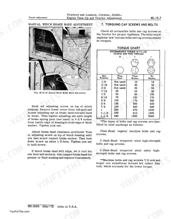
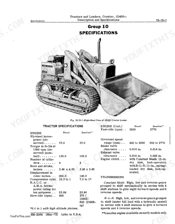
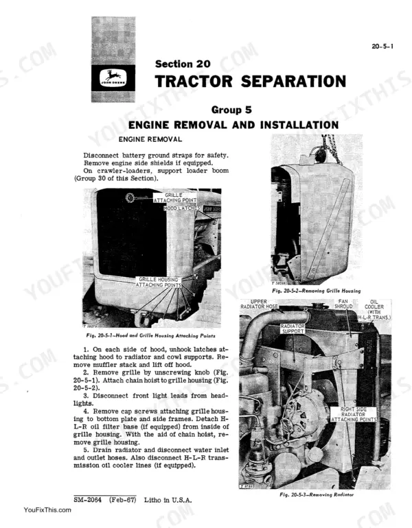
A dragging steering clutch or a loader boom that settles under load will park a JD450 before lunch. The John Deere JD450 service manual PDF runs 572 pages of factory repair data for the crawler tractor and crawler loader, from tractor separation through the No. 3325 power winch. Hydraulic schematics trace the loader control valve and cylinders across both the 15 GPM and 30 GPM pump setups, while the wiring section maps the charging and ignition circuits you test on the machine rather than on the bench. Exploded views fill a long stretch of the book, and the troubleshooting charts start at the symptom. Set track sag at 7/8 to 1-1/8 inch; pull connecting rod cap screws to 60-70 ft-lbs on the diesel, 40-45 on the gasoline engine. Every hour that machine sits is an hour your crew is not moving material. Bookmarked and searchable, so you identify the part before you order it.
What's Inside This John Deere JD450 Manual
| System | Pages | Key Topics |
|---|---|---|
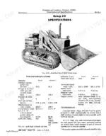
| Description and Specifications | 7-14 | Description, Specifications |
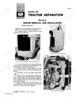
| Tractor Separation | 15-36 | Engine Removal and Installation, Clutch Housing Removal and Installation, Final Drive Removal and Installation, Steering Clutch Removal and Installation |
| Periodic Lubrication | 37-42 | Lubrication Timetable |
| Engine Tune-Up and Tractor Adjustment | 43-72 | Engine Tune-Up, Tractor Adjustment, Loader Adjustment |
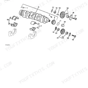
| Engine (Basic) | 73-118 | Cylinder Head, Valves, And Related Parts, Cylinder Block, Cylinder Liners, Pistons, And Connecting Rods, Crankshaft |
| Engine Lubrication System | 119-126 | Oil Pump and Filter |
| Governor and Linkage | 127-134 | Governor, Speed Control Linkage |
| Cooling System | 135-144 | Radiator, Pressure Cap, And Fan Assembly, Water Pump and Thermostat |
| Fuel Systems | 145-186 | Fuel Tank, Fuel Transfer Pump and Fuel Filters, Air Intake System, Carburetor (Marvel-Schebler), Fuel Injection Pumps |
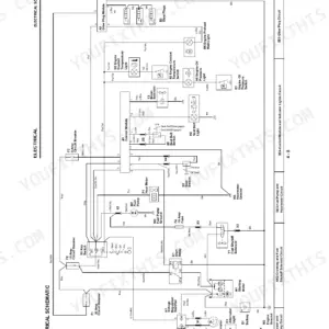
| Electrical System | 187-240 | Fundamentals of Alternator Charging Circuits, Electrical Tests on the Tractor, Ignition System (Gasoline Tractors), Starters, Battery |
| Engine Clutch | 241-248 | Clutch Assembly, Clutch Controls and Clutch Housing |
| Constant Mesh Transmission | 249-302 | Description and Operation, Shifter Mechanism, Range Change Unit, Speed Change Unit and Ring Gear and Hub Assembly |
| H-L-R Transmission | 303-358 | Description and Operation, Range Change Unit |
| Final Drives, Steering Clutch and Brakes | 359-372 | Final Drives, Steering Clutches and Brakes, Steering Clutch Pressure Plate |
| Power Steering System | 373-386 | Power Steering Pump, Power Steering Cylinders, Power Steering Reservoir |
| Track System | 387-408 | Tracks, Track Carrier Assembly |
| Power Take-Off and Winch Drive | 409-412 | Powershaft, Hydraulic Pump, Control Valve, Winch Drum, Brake Band, Clutch Assembly |
| No. 3325 Power Winch | 413-442 | Winch Hydraulic Pump, Control Valve, And Filter, Winch Housing and Component Parts, Winch Fairlead Assembly |
| No. 3320 Manual Winch | 443-472 | Winch Control Valve and Accumulator, Winch Housing and Component Parts, Winch Fairlead Assembly |
| Hydraulic System | 473-520 | Hydraulic Pump (15 GPM), Hydraulic Pump (30 GPM), Loader Control Valve, Hydraulic Cylinders |
| Loader Main Frame, Boom and Buckets | 521-534 | Loader Main Frame and Boom, Digging Bucket, Drott 4-In-1 Bucket |
| Special Service Tools | 561-572 | Engine Service Tool Set, Cylinder Sleeve Puller Set, Diesel Injection Nozzle Kit, Alternator Service Tool Set, Engine Lifting Sling |
Quick Reference Specifications
| Specification | Value | Page |
|---|---|---|
| Cylinder block plate to cylinder block | 20-25 Ft-Lbs | p. 116 |
| Connecting rod cap screws (dip in oil) | 60-70 Ft-Lbs (Diesel), 40-45 Ft-Lbs (Gasoline) | p. 116 |
| Power winch brake band spring anchor pin distance | 4-11/16 inches | p. 65 |
| Manual winch brake spring pack length | 3-3/8 inches | p. 67 |
| Track sag | 7/8 to 1-1/8 inch | p. 389 |
| In-line fuel filter replacement interval (gasoline units) | 500 hours | p. 153 |
| Final drive flanged axle end play | 0.002 to 0.005 inch | p. 364 |
| Final drive pinion shaft preload setting | 0.000 to 0.003 inch | p. 364 |
| Steering lever free travel at top of handle (power steering) | 1-1/2 to 2 inches | p. 371 |
| Grease gun maximum capacity | 8000 psi | p. 389 |
| Fixed tread | 52 inches | p. 387 |
| Bushing outside diameter | 2.0055-2.0065 inches | p. 392 |
John Deere JD450 Common Problems This Manual Covers
John Deere JD450 won't move or steer under load, one track stops pulling
Check steering lever free travel before you pull anything apart. On manual steering it should be 1-1/4 to 1-1/2 inches at the top of the handle, per the specs on page 371; power steering runs 1-1/2 to 2 inches. Back off brakes that self-adjusted tight, then retest both levers under load.
Manual Section: Steering Clutches, Brakes, and Final Drives TroubleshootingEngine loses rpm, runs out of fuel, then dies and won't restart hot
Drain and inspect the fuel filters first, then crack the injection lines at the nozzles and bleed air until fuel runs clean. Replace the in-line filter on gasoline units every 500 hours as noted on page 153, or every 1000 hours with the Airtex transfer pump. Check tank vent and pickup screen.
Manual Section: Engine TroubleshootingBucket won't lift, drifts down, or holds no load after a hydraulic hose blew
Replace the ruptured hose, then refill and bleed the loader circuit before cycling anything under load. Run the machine until oil reaches the normal 150 to 180 degrees F range listed on page 516, then check relief pressure against the 2250 psi loader spec on page 13. Clean the suction screen.
Manual Section: Hydraulic System TroubleshootingTrack throws off the idler, runs loose, or wears the sprocket unevenly
Measure sag in the center of the track between rear sprocket and carrier roller: page 389 calls for 7/8 to 1-1/8 inch. Never use a grease gun rated above 8000 psi on the adjuster. Check track shoe bolt tightness and pin wear before buying new rails.
Manual Section: Track System TroubleshootingEngine governor hunts, surges, or throttle response goes erratic at working rpm
Free up the speed control linkage and check every pivot for binding before you condemn the pump. Work through the governor section starting on page 127, then inspect the injection pump flex ring. If you open the pump, torque the advance hole plug to 70-80 in-lbs on Model C units.
Manual Section: Governor and Linkage p. 127Final drive seal leaking oil onto the brake drum, machine pulls to one side
Pull the final drive and set flanged axle end play to 0.002 to 0.005 inch with the slotted nut, as page 364 spells out. Torque the pinion shaft quill cap screws to 85 ft-lbs and the final drive housing bolts to 170 ft-lbs. Replace both seals, not just the leaker.
Manual Section: Final Drives, Steering Clutch and Brakes p. 359Frequently Asked Questions
What is the torque specification for the cylinder head cap screws on the JD450 engine?
The cylinder head cap screws must be tightened evenly to 110 ft-lbs torque, following the exact sequence shown in the manual. p. 82
What are the replacement specifications for the steering clutches on a John Deere JD450?
The steering clutches are dry, multiple-disk types. Each clutch has 16 friction surfaces. The lever free travel at the top of the handle should be 1-1/4 to 1-1/2 inches on units with manual steering, or 1-1/2 to 2 inches on units with power steering. p. 371
What is the correct valve clearance for the JD450 diesel engine?
The valve clearance for the diesel engine, whether hot or cold, is 0.014 inch for the intake valves and 0.018 inch for the exhaust valves. p. 73
How often should I drain and refill the engine crankcase on a John Deere JD450?
The engine crankcase should be drained and refilled every 100 hours of operation. p. 39
What is the correct fuel injection pump timing for the Roosa-Master Model DB pump?
The timing line on the weight retainer hub must align with the timing line on the cam when the engine is at top dead center (No. 1 cylinder on compression stroke). p. 174
What exactly do I receive with this John Deere JD450 Service Manual?
You download the Service Manual yourself: 572 pages, searchable PDF, available immediately. Keep a copy on every device you use.
Am I able to print pages from this John Deere JD450 manual?
Yes, printing is unrestricted: a single page, a chapter, or the lot, on letter or A4.








Reviews
There are no reviews yet.