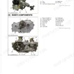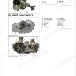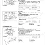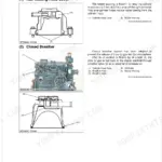


Part of the Kubota Repair Manuals.
This is the factory Kubota Workshop Manual for the B3300SU-AUS compact tractor, a 337 page PDF built around the three cylinder V1505-E024H diesel engine.
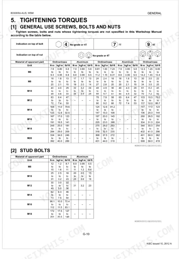
It walks through every system with mechanism descriptions and full servicing procedures: engine, clutch, the hydrostatic transmission and PTO drive, rear and front axles, brakes, power steering, the hydraulic system with its loader and three point hitch valves, and the electrical system with wiring diagrams. Troubleshooting charts, servicing specifications, and tightening torques accompany each section, including wheel nut and cylinder head bolt figures.
For owners and independent shops this is the same reference used to diagnose an HST whine, trace a starting fault, or carry out a complete teardown and reassembly with the correct clearances and torque values.
What's Inside This Kubota B3300SU-AUS Manual
| System | Pages | Key Topics |
|---|---|---|
| General | Tractor Identification, Model Name and Serial Number, Cylinder Number, General Precautions, Wiring, Battery, Fuse, Connector | |
| Engine | Tractor Section, Engine Section, Engine Body, Lubricating System, Cooling System, Fuel System, Preparation, Separating Engine From Clutch Housing | |
| Clutch | Cylinder, Oil Pump, Linkage Mechanism, Operation, Preparation, Separating Engine From Clutch Housing | |
| Transmission | Power Train for Travelling System, Hydrostatic Transmission, Power Train for PTO Gear, Rear PTO Section, Preparation, Separating Engine From Clutch Housing, Separating HST Assembly, Disassembling Clutch Housing | |
| Rear Axle | Transmission Case, Differential Gear, Differential Gear Shaft, 57T Spur Gear, Ball Bearing, Rear Axle Case, Spiral Bevel Gear | |
| Brakes | Linkage, Operation, Brake Pedal | |
| Front Axle | Separating Front Axle | |
| Steering | Steering Linkage, Power Steering, Hydraulic Circuit for Power Steering System, Preparation, Hydraulic Pump for Power Steering, Separating Power Steering Assembly, Power Steering Body | |
| Hydraulic System | Hydraulic Circuit, Hydraulic Pump, Control Valve Assembly, Front Loader Control Valve, 3-Point Hitch Control Valve, Shim, Relief Valve, 3-Point Hitch Hydraulic System | |
| Electrical System | Wiring Diagram, Engine Starting System and Stopping System, Opc System Circuit, Controller, Safety Switch and Engine Condition, Lighting System, Head Light, Turn Signal Light and Hazard Light |
Every system also includes servicing, tightening torques, and troubleshooting.
Documents This Manual Refers To
The manufacturer cites these publications by number. We carry them:
Quick Reference Specifications
| Specification | Value | Page |
|---|---|---|
| Front wheel mounting nut torque | 79 to 92 N·m (8.1 to 9.4 kgf·m, 59 to 67 lbf·ft) | p. 228 |
| Rear wheel mounting nut torque | 146 to 150 N·m (14.8 to 15.3 kgf·m, 107 to 110 lbf·ft) | p. 200 |
| Cylinder head screw torque | 64 to 68 N·m (6.5 to 6.9 kgf·m, 47 to 50 lbf·ft) | p. 98 |
| Transmission fluid type | KUBOTA UDT or SUPER UDT fluid | p. 23 |
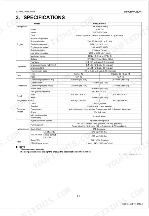
| Transmission fluid capacity | 14.5 L (3.83 U.S. gals, 3.19 Imp.gals) | p. 23 |
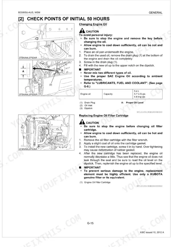
| Engine oil filter replacement interval | Replace at 50 hours | p. 27 |
| Transmission oil filter replacement interval | Replace at 200 hours | p. 27 |
| Fuel filter element replacement interval | Replace at 200 hours | p. 27 |
| Air cleaner element (primary) cleaning interval | Clean at 50 hours | p. 27 |
| Air cleaner element (secondary) replacement interval | Replace at 200 hours | p. 27 |
| Battery type | 55B24L(S)-MF | p. 36 |
| Battery voltage | 12 V | p. 36 |