

Part of the Kubota Repair Manuals.
This Kubota ZG327P Shop Manual is the 268-page factory workshop reference for the ZG327P zero-turn mower, powered by the KGZ770-E2-M1 gasoline engine. It documents this specific machine rather than a generic model family, so the procedures and specifications match what is on your unit.
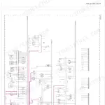
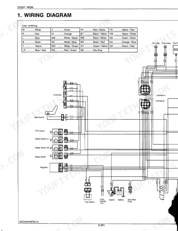
The manual is organized by system: engine, transaxle with hydrostatic transmission, front axle, hydraulics, electrical, and the mower deck. It carries full specification and torque tables, the wiring diagram, and step by step disassembly and reassembly procedures, plus maintenance check points from the daily inspection through the 400 hour interval.
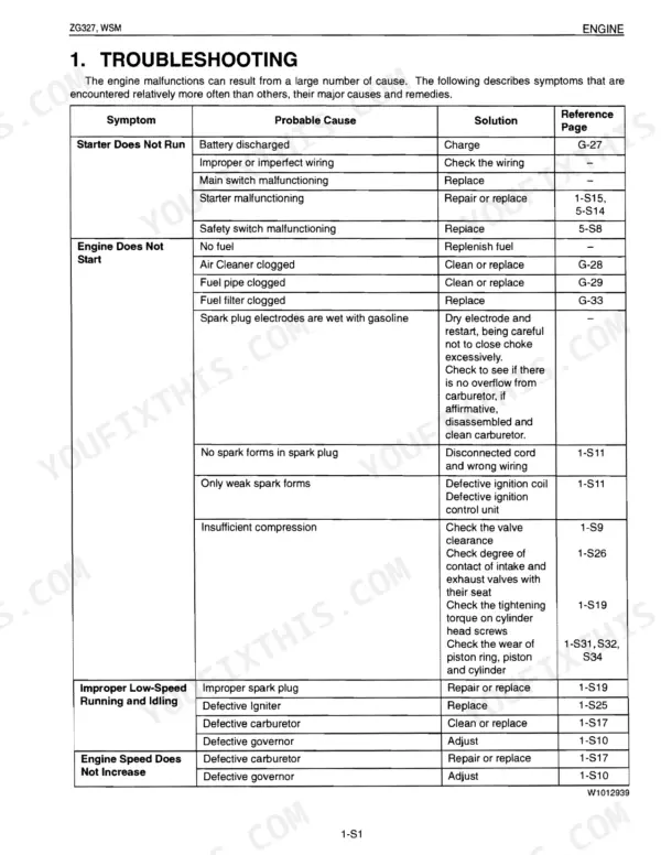
Owners and independent mechanics can use it to trace a no start, rebuild or diagnose the HST, set valve clearance, check the charging and starting circuits, or service the mower drive. It is delivered as a downloadable PDF you can view on any device or print.
What's Inside This Manual
| System | Pages | Key Topics |
|---|---|---|
| Intro | 1-12 | SAFETY FIRST, BEFORE SERVICING AND REPAIRING, SAFETY STARTING, SAFETY WORKING, AVOID FIRES, VENTILATE WORK AREA, PREVENT ACID BURNS, DISPOSE OF FLUIDS PROPERLY, PREPARE FOR EMERGENCIES, SAFETY DECALS |
| General | 13-60 | Identification, Cylinder Number, Handling Precautions for Electrical Parts and Wiring (Battery, Fuse, Connector, Handling of Circuit Tester), Lubricants and Fuel |
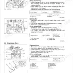
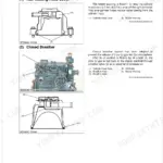
| Sect 1 Engine | 61-112 | Feature, Engine Body (Cylinder Head, Closed Breather, Camshaft, Combustion Chamber, Piston and Piston Ring, Gear Train Made of Reinforced Nylon) |
| Sect 2 Transaxle | 113-166 | Travelling System, Hydrostatic Transmission, Check Valve and High Pressure Relief Valve, Power Trains Operation, Control Linkage, Final Reduction Gear Section, PTO System, Parking Brake |
| Sect 3 Front Axle | 167-176 | Separating Front Wheel and Wheel Bracket, Remove the Front Wheel, Remove the Wheel Bracket |
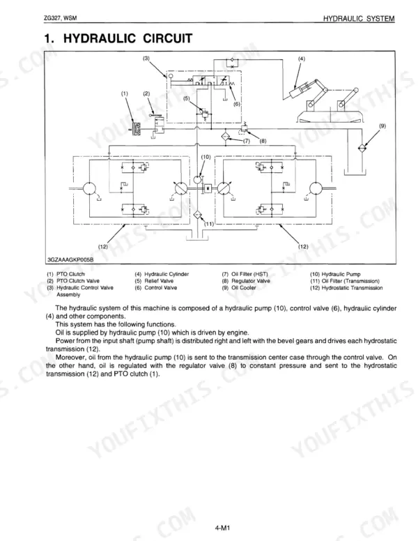
| Sect 4 Hydraulic | 177-202 | Hydraulic Circuit, Hydraulic Pump, Hydraulic Control Valve, Lift Cylinder, Mower Linkage |
| Sect 5 Electrical | 203-250 | Wiring Diagram, Starting System (Starter, Safety Switch, Relay, Fuel Pump, Fuel Cut Off Solenoid), Charging System (Generator, Regulator, Easy Checker), Gauges (Fuel Quantity) |
| Sect 6 Mower | 251-268 | Power Transmission |
Quick Reference Specifications
| Specification | Value | Page |
|---|---|---|
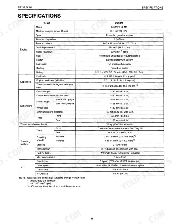
| Fuel tank capacity | 49 L | p. 22 |
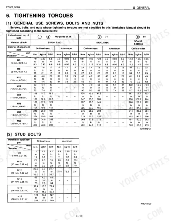
| M6 (Standard Screw and Bolt) tightening torque | 7.9 to 9.3 N·m | p. 24 |
| Engine Oil Capacity (with filter) | 2.0 L | p. 9 |
| Mower blade spindle speed | 3360 min-1 (rpm) | p. 10 |
| Valve Clearance (Cold) Intake | 0.12 to 0.17 mm | p. 79 |
| Compression Pressure (No. 1 Cylinder) | 1.19 MPa | p. 79 |
| Engine Oil Pressure (At Rated Speed) | 294 to 441 kPa | p. 82 |
| Spark Plug Air Gap | 0.60 to 0.70 mm | p. 82 |
| Cylinder head screw torque (M10 x 1.5) | 41.2 to 50.0 N·m | p. 83 |
| Flywheel screw torque (M12) | 100 to 120 N·m | p. 83 |
| Connecting rod screw torque (M8 x 1.25) | 21.6 to 27.4 N·m | p. 83 |
| Parking Brake Spring Play | 0.5 to 1.0 mm | p. 140 |