Part of the New Holland Repair Manuals.
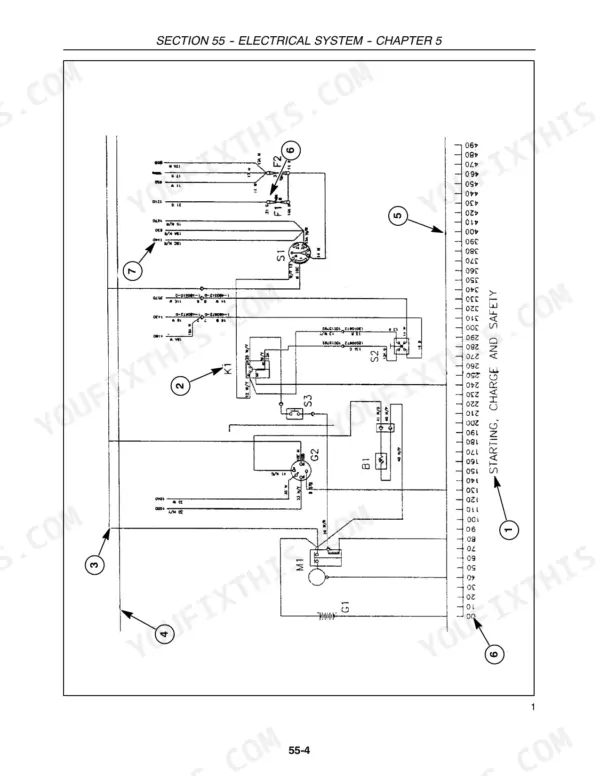
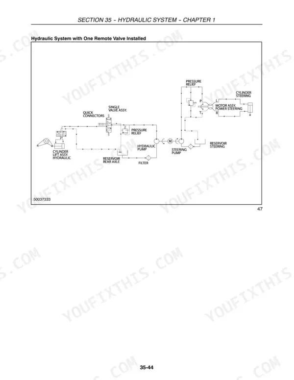
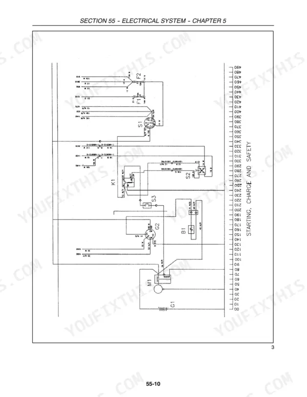
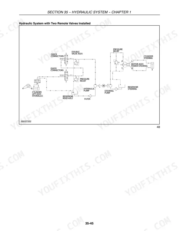
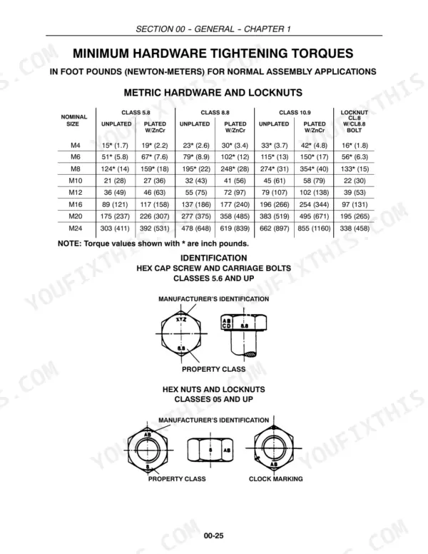
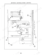
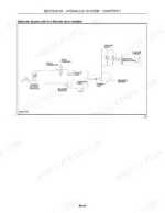
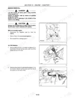
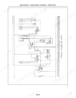
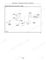
Printed by New Holland under part number 87042097, this 432-page factory book is the genuine New Holland TT55, TT75 repair manual PDF for both tractors. Linear wiring diagrams trace the starting, charging and safety circuits, the thermostart and injection pump feed, and every lamp and flasher run, while hydraulic schematics show oil routing with one, two or three remote valves installed. From splitting the tractor to injector sleeve replacement, your engine overhaul is laid out in full, and that detail carries into the clutch, 4WD front axle bevel drive, final drives, brakes and hydrostatic steering motor. Press the water pump impeller on with 0.017 to 0.059 mm of interference, and bring the rim to disc nuts up to 245 N·m (181 ft.lbs.). Per-system bookmarks and a searchable text layer jump you straight to the lift adjustment checks.
What's Inside This Repair Manual
| System | Pages | Key Topics |
|---|---|---|
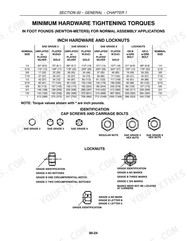
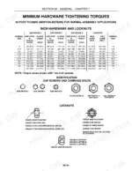
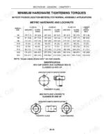
| General | 2-46 | Health and Safety, Precautionary Statements, Safety, Ecology and the Environment, Minimum Hardware Tightening Torques, Tractor System Components, Speed Chart |
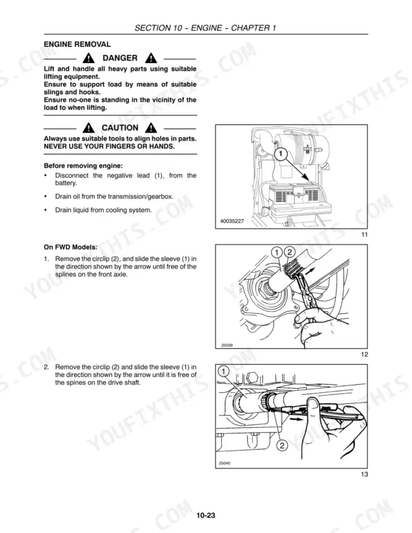
| Engine | 47-160 | Engine Overhaul (Tightening Torque Data, Engine Special Tools, Engine Sectional Views) |
| Clutches | 161-168 | Specifications, Clutch Assembly Removal/Installation, Clutch Overhaul, Transmission Clutch Pedal Free-Travel and Adjustment, PTO Clutch Linkage |
| Front Transmission | 169-186 | Specifications, Transmission Removal and Installation, Inspecting the Transmission, Assembling the Transmission |
| Four Wheel Drive (FWD) Transfer Box | 187-190 | Transfer Box and Axle Shaft |
| Four Wheel Drive (FWD) Front Axle | 191-220 | Four-Wheel Drive Front Axle Specifications, Special Tools, Four-Wheel Drive Front Axle Special Tools, Four-Wheel Drive Front Axle - Description and Operation |
| Rear Axle and Transmission | 221-236 | Special Tools, Rear Transmission Housing Removal/Installation, Bevel Drive and Differential Removal, Reassembling the Bevel Drive and Differential, Final Drive, Final Drive Removal |
| Power Take-Off (PTO) | 237-242 | Specifications, PTO Operation, PTO Removal and Installation |
| Brake System | 243-250 | Brakes (Specifications, Description and Operation, Brake Pedal Free-Travel/Adjustment, Parking Brake T-Handle Free-Travel/Adjustment, Brake Disassembly) |
| Hydraulic System | 251-296 | Hydraulic Lift Specifications, Special Tools, Hydraulic System Precautions, Description and Operation, Remote Control Valves, Remote Valve Control Levers, Quick-Fit Couplers |
| Steering System | 297-330 | Steering System Specifications, Description and Operation, Steering System Testing and Adjustment, Determining Front Wheel Toe in/Toe Out, Hydrostatic Steering Motor Overhaul |
| 2WD Front Axle | 331-338 | 2WD Front Axle and Steering Specifications, Two-Wheel Drive Front Axle and Steering Special Tools, Front Axle Repair, Front Axle Removal and Installation, Steering Knuckle Overhaul |
| Electrical System | 339-422 | Description and Operation (Fault Finding, Precautionary Statements, Electrical System - Description and Operation) |
| Bodywork | 423-432 | Engine Hood Panel Assembly, Rear Wheel Fenders, Roll-Over Protection Bar, Battery Removal, Installation |
Quick Reference Specifications
| Specification | Value | Page |
|---|---|---|
| Nut For Rim to Disc Securing Bolt | 245 N·m (181 ft.lbs.) | p. 195 |
| Air Cleaner Tube Clamps Torque | 2.0 N·m (18 in.-lb.) | p. 156 |
| Pump Interference Install Between Impeller and Shaft | 0.017 to 0.059 mm (0.0007 to 0.0023 in.) | p. 51 |
| Pump Interference Install Between Fan Hub and Shaft | 0.024 to 0.058 mm (0.0009 to 0.0023 in.) | p. 51 |
| Shaft Clearance in Bushing | 0.050 to 0.100 mm (0.0020 to 0.0040 in.) | p. 57 |
| Bushing Interference Install in Housing | 0.063 to 0.140 mm (0.0025 to 0.0055 in.) | p. 57 |
| Thermostat Starts Opening | 79° C ± 2° C (174° F ± 3.6° F) | p. 51 |
| Thermostat Fully Open | 94° C (201° F) | p. 51 |
| Shaft Clearance in Driven Gear | 0.033 to 0.066 mm (0.0013 to 0.0026 in.) | p. 50 |
| Gear Backlash | 0.100 mm (0.0039 in.) | p. 57 |
| Cylinder head bolts | 70 N·m (7.1 kgm, 52 ft. lbs.) preliminary torque, followed by 90° + 90° angle | p. 59 |
| Nuts for injector mounting studs | 25 N·m (2.6 kgm, 19 ft. lbs.) | p. 2 |