
Part of the Yanmar Repair Manuals.
Shut the machine down and let the pressure bleed off before you crack a fitting on a Yanmar V7 or V8 wheel loader; the cautions for hydraulic removal, seal handling and air release that open this service manual exist because skipping them wrecks parts. This is Yanmar factory publication MM548ENWL00101, 213 pages in English, written around the 4TN88DSA2 diesel that powers both machines.
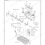
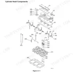
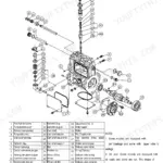
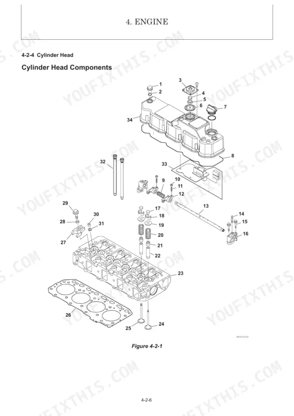
The Engine chapter takes you through cylinder head work, valve clearance, fuel injection pump service and timing, cooling, lubrication, starter and alternator. The Hydraulic System chapter covers the loader and steering circuits, the hydrostatic transmission, the valve setting chart, a towing procedure and troubleshooting. Technical Data holds the specifications, lifting capacity list, fluid recommendations, hydraulic schematic and electrical diagram.
Guessing at a relief pressure or a torque value on a loader that earns its keep daily gets expensive fast. The PDF is a one-time download, yours to keep for this machine, printable page by page for the bench.
Complete the set for your V7, V8
- Parts Catalog: Yanmar V7 Parts Catalog (Wheel Loader)
What's Inside This Manual
| System | Pages | Key Topics |
|---|---|---|
| General Cautions for Maintenance Work | 8-16 | Correct Work, Safety Precautions, Preparations, Cautions for Disassembly and Reassembly, Cautions for Removal and Installation of Hydraulic Equipment |
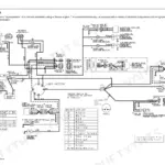
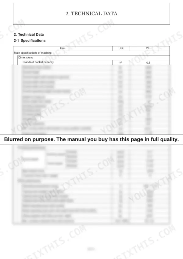
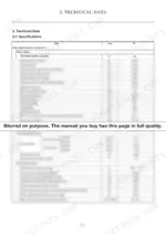
| Technical Data | 20-31 | Machine Specifications, Outline Drawing, Lifting Capacity, Periodic Inspection, Fluid Recommendations, Hydraulic Circuit Schematic, Electrical Diagram |
| Service Standards | 34-35 | Machine Performance, Bucket Speed, Arm Lifting Speed, Parking Brake Performance |
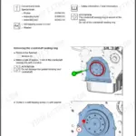
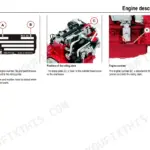
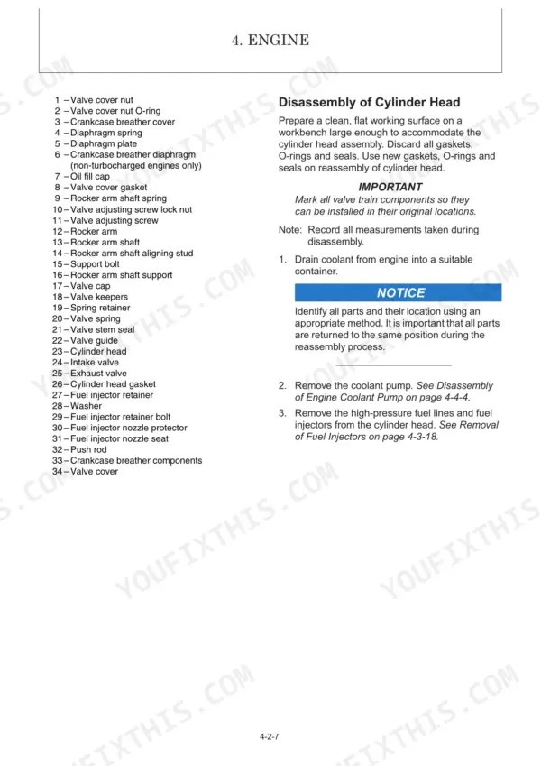
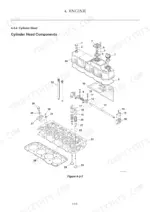
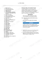
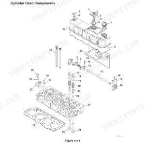
| Engine | 38-181 | Safety Statements, Special Service Tools, Cylinder Head, Fuel System, Cooling System, Lubrication System, Starter Motor, Alternator |
| Electric System | 184-191 | Electric Equipment of Machine (Localisation of Fuse and Relays, Identification of Fuses, Identification of Relays, Identification of Connectors) |
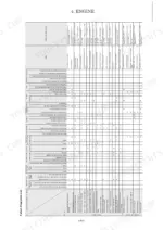
| Hydraulic System | 194-211 | Hydraulic Circuit, Valve Setting Chart, Circuit Operation (Loader, Steering), Hydrostatic Transmission, Pressure Control, Towing Procedure, Troubleshooting |
Quick Reference Specifications
| Specification | Value | Page |
|---|---|---|
| Fuel injector retainer bolt torque | 39.2 N·m | p. 101 |
| Fuel pump drive gear nut torque | 78 - 88 N·m | p. 101 |
| Distributor tie rods driving torque | 2.5 – 2.8 KGM (18 – 20 LB.FT) | p. 197 |
| Radiator fan blade dimensions | 7 blades × Ø380 mm | p. 23 |
| Operating temperature of water temperature alarm switch | 107 to 113 ºC | p. 23 |
| Temperature switch continuity range | 107 °C - 113 °C | p. 134 |
| Standard bucket capacity | 0.8 m³ | p. 20 |
| Operating mass (cabin) | 4350 kg | p. 20 |
| Intake valve clearance (Cold engine) | 0.15 to 0.25 mm | p. 22 |
| Hydraulic pump Max. pressure | 35.0 MPa | p. 25 |
| Hydraulic oil tank capacity | 60 L | p. 25 |
| Thermal engine oil capacity | 8 L | p. 29 |