
Part of the Case Repair Manuals.
A shuttle grinding into reverse can park your tractor in the middle of planting. This Case 430 service manual PDF, Case publication 9-75304, answers that job with 579 factory pages covering four tractor models in spark ignition and diesel builds. Wiring diagram supplements map the generator, ignition, and cranking circuits for each model pair, while hydraulic schematics trace the Draft-O-Matic system from the 10 GPM pump through the remote valves and breakaway couplings. Rebuild procedures carry the Roosa Master DB injection pump, the mechanical shuttle, and the Case-O-Matic drive down to final clearances. Check the oil pump relief valve against its 50 to 75 pound rating on the 188 diesel, then pull your connecting rod nuts to 45 to 50 ft. lbs. on reassembly. A misremembered torque snaps a stud the co-op cannot order. Bookmarked and text searchable, this PDF puts the right spec on screen in seconds and gets the tractor back in the field.
Other edition of this manual
What's Inside This Case 430, 530, 470, 570 Manual
| System | Pages | Key Topics |
|---|---|---|
| General | 3-18 | Specifications, Torque Specifications |
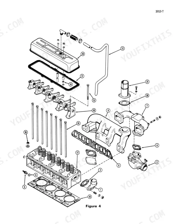
| Engines | 19-148 | Cylinder Head and Valves - Spark Ignition, Cylinder Head and Valves - Diesel, Cylinder Block Assembly - Spark Ignition, Cylinder Block Assembly - Diesel |
| Fuel System | 149-250 | Fuel System and Filters - 188 and 207 Diesel Engines, Fuel Strainer and Filter - Spark Ignition Engines, Roosa Master Db Fuel Injection Pump, Roosa Master Fuel Injectors |
| Hydraulics | 251-306 | Portable Hyd. Cyl. and Break Away Couplings, Servicing the Remote Hydraulic Valves, Servicing the Hydraulic Pump, Draft-O-Matic Hydraulic System |
| Steering | 307-380 | Hydrostatic Steering System, Power Steering System, Mechanical Steering System, Packing Front Wheel Bearings, Servicing the Front Axle |
| Power Train | 381-495 | Four Speed Transmission and Final Drive, Servicing the Mechanical Shuttle, Dual Range Assembly, Splitting the Tractor at Torque Tube and Transmission, Inch Traction Clutch |
| Brakes | 496-507 | Differential Brakes, Parking Brake and Adjustment |
| Electrical | 508-579 | Supl. No. 3 Wiring Diagram - 430-470, Supl. No. 4 Wiring Diagram - 530-570, Electrical System, Generator System, Distributor Ignition System, Starting and Cranking Motors |
Quick Reference Specifications
| Specification | Value | Page |
|---|---|---|
| Camshaft Nut | 80-90 Ft. Lbs. | p. 9 |
| Connecting Rod Nut | 45-50 Ft. Lbs. | p. 9 |
| Oil Pump Pressure Relief Valve | 50 to 75 Pounds | p. 5 |
| Relief Valve Spring Pressure at Compressed Height of 1.438 Inches | 18.4 Pounds | p. 16 |
| Pump flow | 10 GPM | p. 274 |
| Pump cover bolt torque | 28-32 foot pounds | p. 276 |
| Power Pump Oil Flow | 6.5 GPM at 1200 PSI | p. 336 |
| Power Pump Relief Valve Pressure | 1500 to 1700 PSI | p. 306 |
| End cover bolt torque | 18 to 22 foot pounds | p. 332 |
| Ball stud retainer plate screw torque | 5 to 7 foot pounds | p. 334 |
| Rear cover torque | 9 - 11 foot pounds | p. 356 |
| Pressure spring rate | 95 to 105 lbs. at height of 1.685" | p. 438 |
Case 430, 530, 470, 570 Common Problems This Manual Covers
Case 430 three-point hitch lifts slowly, heavy implements will not raise off the ground
Check main system pressure first: tee a gauge into the pump outlet, dead-head the lift, and read 1450 to 1550 PSI at the relief valve, the spec on page 274. If pressure is low, adjust the relief valve and verify pump flow against the 10 GPM rating. Milky oil in the rearend means internal leakage; drain both housings and reseal.
Manual Section: Servicing the Hydraulic Pump p. 274Steering feels weak and wanders, fluid leaking from both steering cylinders and the pump
Check power steering pump relief pressure with a gauge; spec is 1500 to 1700 PSI, listed on page 308. Verify pump output next; a healthy pump moves 6.5 GPM per page 336. If flow is low, replace the pump. Rebuild leaking cylinders with new seals and torque the ball stud retainer plate screws to 5 to 7 foot pounds.
Manual Section: Hydrostatic Steering System p. 308Clutch will not fully disengage, gears grind and tractor creeps with pedal down
Split the tractor at the torque tube to get at the clutch, following the procedure in the Power Train section starting on page 381. Measure the pressure springs; they should test 95 to 105 lbs. at a height of 1.685 inches per page 438. Replace the disc and pressure plate as a set, then refill the transmission with 17 quarts of oil.
Manual Section: Power Train p. 381Engine cranks slowly, starts hard in cold weather, battery seems dead every morning
Test the battery with a specific gravity check and capacity test as covered in the Electrical section starting on page 508. Clean and tighten both ground connections. If cranking speed is good but the diesel still starts hard, run a compression test; the 188 diesel should show 400 PSI at sea level, listed on page 4.
Manual Section: Electrical p. 508Engine runs rough and lacks power under load, steady ticking from the top end
Pull the valve cover and check tappet clearance with the engine cold. On the 188 diesel, set clearance to .014 inch, the spec listed on page 5. Adjust any loose rockers, then recheck after the next day in the field. If clearance will not hold, inspect the cam followers using the cylinder head procedure starting.
Manual Section: Cylinder Head and ComponentsFrequently Asked Questions
What are the clutch disc replacement specifications for the Case 430, 530, 470, 570 tractor?
The disc assembly must be carefully inspected for worn hub splines, distortion of the disc, cracks, and worn facing. If the disc is damaged or the facings are worn, it must be replaced. p. 438
What is the torque specification for the cylinder head nuts on a Case 188 Diesel engine?
For the 188 Diesel engine, the cylinder head nuts should be torqued to 110-120 ft. lbs. p. 9
What is the correct valve tappet clearance for the 188 Diesel engine in Case 430, 530, 470, 570 tractors?
The valve tappet clearance for the 188 Diesel engine is .014 inch, both for cold and hot engine settings. p. 5
What is the recommended service interval for the fuel strainer on a Case 430, 530, 470, 570 tractor?
The fuel strainer should be serviced every 200 hours. p. 153
What is the correct torque for the transmission to torque tube bolts on a Case 430, 530, 470, 570?
The transmission to torque tube bolts should be torqued to 80 to 132 ft. lbs. p. 382
Do I get instant access to this Case 430 Service Manual?
Immediate download of the complete 579-page searchable Service Manual. Access it on any device, from a laptop at your desk to a phone in the field.
Can I print this Case 430 manual?
Yes. Print the sections you need to take out to the shop for your own use. Standard letter or A4 paper works.









Reviews
There are no reviews yet.