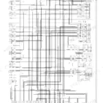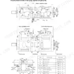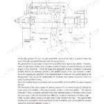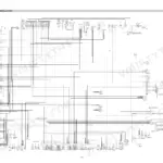


Part of the Hyundai Repair Manuals.
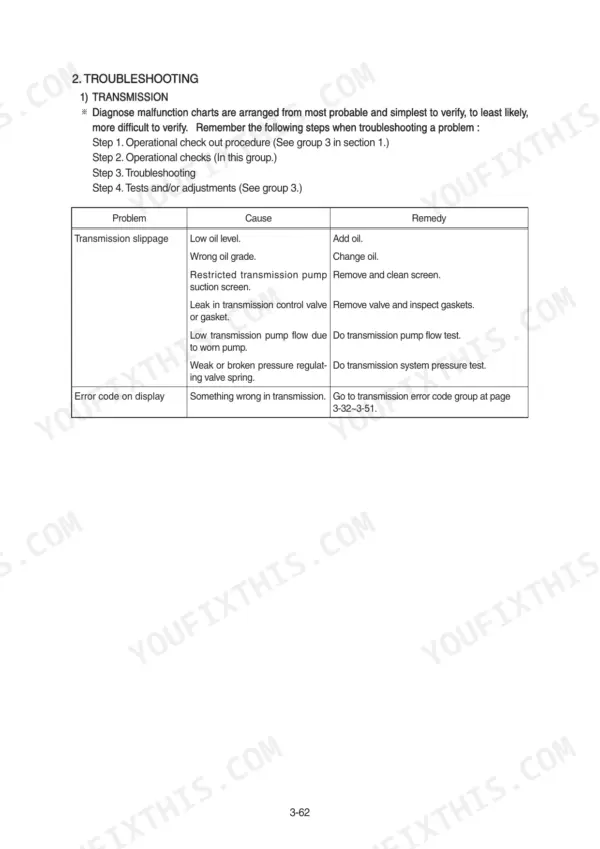
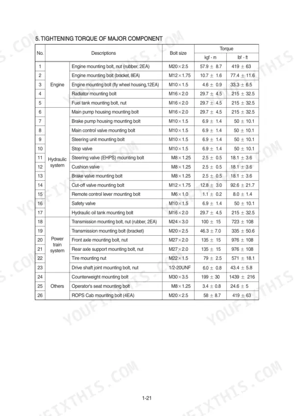
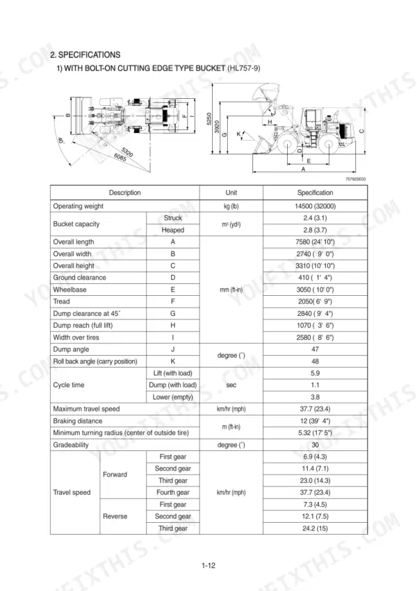
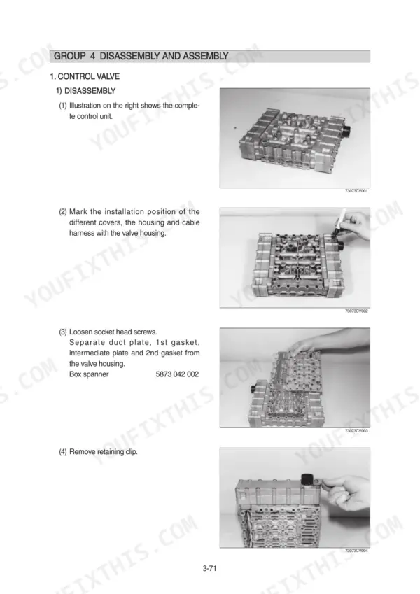
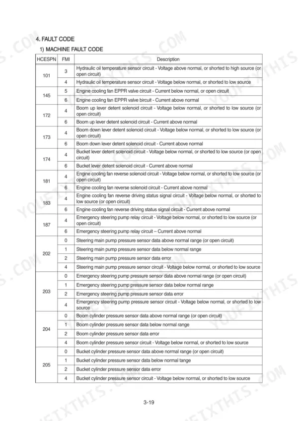
Need factory answers for your Hyundai HL757-9, HL757XTD-9, or HL757TM-9 wheel loader? This 545-page service manual PDF covers all three variants front to back: engine, power train, brakes, steering, work equipment, and the complete electrical system. You get full wiring circuits with connector pinouts and component locations, hydraulic schematics with fluid routing, error code tables, and troubleshooting charts for every major system. Page after page of disassembly and assembly procedures walk you through each rebuild the way Hyundai engineers wrote them. Torque the EHPS steering valve mounting bolts to 2.5 kgf·m (18.1 lbf·ft) and check the brake gear pump against its 150 kgf/cm2 maximum delivery pressure. No more chasing electrical gremlins with a multimeter and a prayer. Bookmarked by system and keyword-searchable, the PDF opens on any device you carry into the shop.
What's Inside This Manual
| System | Pages | Key Topics |
|---|---|---|
| General | 1-38 | Safety Hints, Specifications, Operational Checkout Record Sheet |
| Engine | 39-47 | Structure and Function, Fuel Warmer System, Engine Speed and Stall RPM |
| Power Train System | 48-260 | Power Train Component Overview, Torque Converter, Transmission Layout and Installation, Operation of Transmission, Electro-Hydraulic Shift Control, Gear Selector, Electronic Control Unit, Transmission Disassembly and Assembly |
| Brake System | 261-307 | Brake Hydraulic Circuit, Service Brake Released and Operated, Parking Brake Released and Operated, Brake Pump, Principle of Operation, Brake Tests and Adjustments |
| Steering System | 308-367 | Steering Hydraulic Circuit, Steering Unit, EHPS Steering Valve, Neutral, Left Turn and Right Turn Operation, Steering Tests and Adjustments |
| Work Equipment | 368-459 | Hydraulic System Outline, Work Equipment Hydraulic Circuit, Main Pump Structure and Function, RCV Lever Positions (Raise, Lower, Float, Dump, Roll), Cylinder Drift and Cycle Time Tests |
| Electrical System | 460-545 | Component Location, Electrical Circuit, Monitoring System, Electrical Component Specification, Connectors, Troubleshooting |
Quick Reference Specifications
| Specification | Value | Page |
|---|---|---|
| Steering valve (EHPS) mounting bolt torque | 2.5 ± 0.5 kgf·m (18.1 ± 3.6 lbf·ft) | p. 33 |
| Brake valve mounting bolt torque | 2.5 ± 0.5 kgf·m (18.1 ± 3.6 lbf·ft) | p. 33 |
| Maximum delivery pressure | 150 kgf/cm2 | p. 270 |
| Diameter | 138 mm | p. 278 |
| Mounting height | 187 mm | p. 278 |
| Body bore cut-in depth | 0.15 mm (0.006") | p. 301 |
| Maximum pressure at steering valve (EHPS) | 4.5 MPa (45 bar, 640 psi) | p. 334 |
| Steering valve (EHPS) oil pressure | 24.5 ± 0.05 MPa (250 ± 5 bar, 3560 ± 71 psi) | p. 336 |
| Tightening torque for six screws with washers | 3.1 ± 0.6 kgf·m (22.4 ± 4.3 lbf·ft) | p. 354 |
| Tightening torque for Gland | 56 ± 6 kgf·m (405 ± 43.4 lbf·ft) | p. 356 |
| Tightening torque for Piston | 90 ± 9 kgf·m (650 ± 65.1 lbf·ft) | p. 356 |
| Bypass valve set pressure | 1.36 kg/cm2 (19.3 psi) | p. 408 |