
![Hyundai HSL800T Repair Manual [Skid Steer Loader]](https://youfixthis.com/wp-content/uploads/2016/02/2016-02-16_11-07-01-1-300x300.jpg)

Part of the Hyundai Repair Manuals.
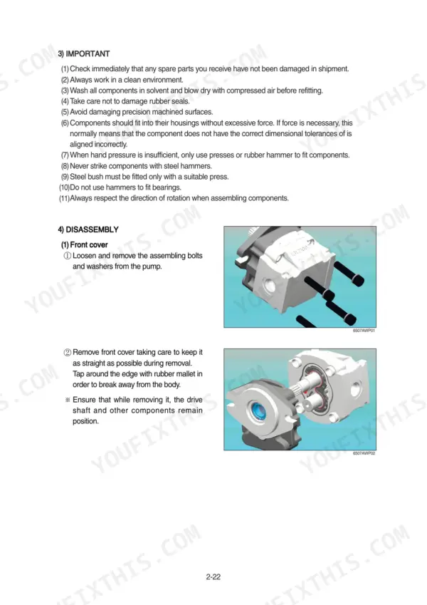
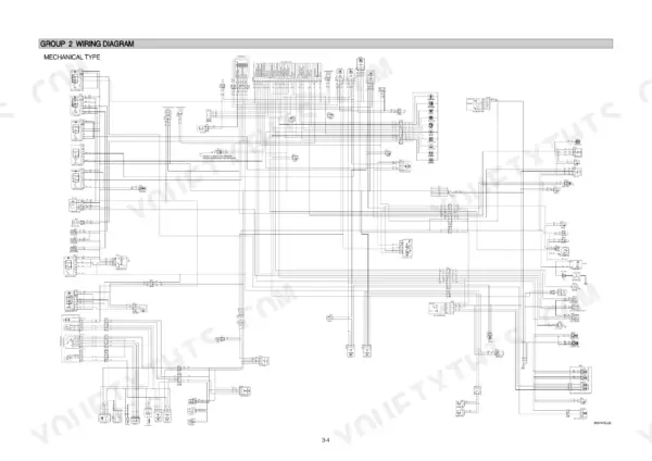
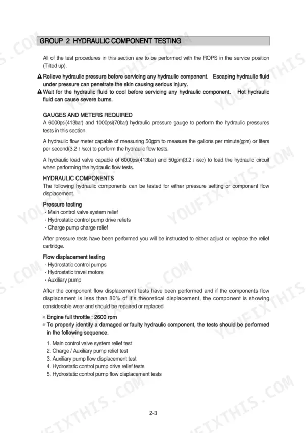
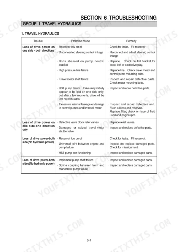
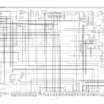
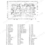
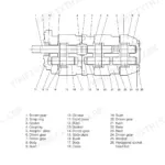
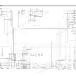
Need factory data for your Hyundai HSL850-7A skid steer loader? This 180-page Hyundai HSL850-7A service manual PDF walks you through the HST pump (mechanical and pilot types), travel motor, self level valve, and boom and bucket cylinders from teardown to reassembly. You get hydraulic circuit diagrams with component pressure and flow testing steps, full wiring diagrams with electrical component locations, exploded views of the auxiliary pump internals, and a troubleshooting section covering travel hydraulics, power train, and controls. Torque the auxiliary pump bolts to 3.7-4.2 kgf.m (26.8-30.4 lbf.ft) and pull the front cover bolts down to 14.3 kgf.m (103 lbf.ft). No more diagnosing a weak drive side on guesswork. Bookmarked with a live text layer: jump straight to a section, search any spec by keyword, and pull it up on your phone next to the machine.
What's Inside This Hyundai HSL850-7A Manual
| System | Pages | Key Topics |
|---|---|---|
| General | 1-21 | Safety Hints, Specifications, Maintenance |
| Hydraulic Circuit and Component Testing | 22-35 | Hydraulic Circuit Diagrams, Mechanical Type Testing, Pilot Type Testing, Component Pressure Testing, Flow Displacement Testing |
| Self Level Valve and Auxiliary Pump | 36-57 | Self Level Valve Structure, Self Leveling Operation, Auxiliary Pump Removal and Installation, Tandem Auxiliary Pump, Pump Disassembly and Assembly |
| HST Pump (Mechanical and Pilot Types) | 58-84 | HST Pump Removal and Installation, HST Pump Structure, General Description, Transmission Hydraulic Support System, Troubleshooting, Inspection and Adjustments |
| Travel Motor | 85-129 | Travel Motor Removal and Installation, Travel Motor Structure, Disassembly and Assembly, Brake Motor Disassembly, Brake Motor Assembly |
| Boom and Bucket Cylinder | 130-134 | Boom Cylinder Removal and Installation, Bucket Cylinder Removal and Installation, Cylinder Structure, Cylinder Disassembly, Cylinder Assembly |
| Electrical System | 135-157 | Component Location, Wiring Diagram |
| Power Train | 158-163 | Power Train Component, Front and Rear Axle |
| Control | 164-171 | Mechanical Control, Pilot Control, Attachment Holder |
| Troubleshooting | 172-180 | Travel Hydraulics, Boom and Bucket Hydraulic, Power Train, Control, Electrical System |
Quick Reference Specifications
| Specification | Value | Page |
|---|---|---|
| Flare type fitting torque (SAE size 4) | 1.1 - 1.6 kgf·m (8.3 - 11.7 lbf·ft) | p. 17 |
| Flare type fitting torque (SAE size 6) | 2.6 - 3.1 kgf·m (18.8 - 22.9 lbf·ft) | p. 17 |
| Battery specification | 1 x 12V x 100~120Ah | p. 13 |
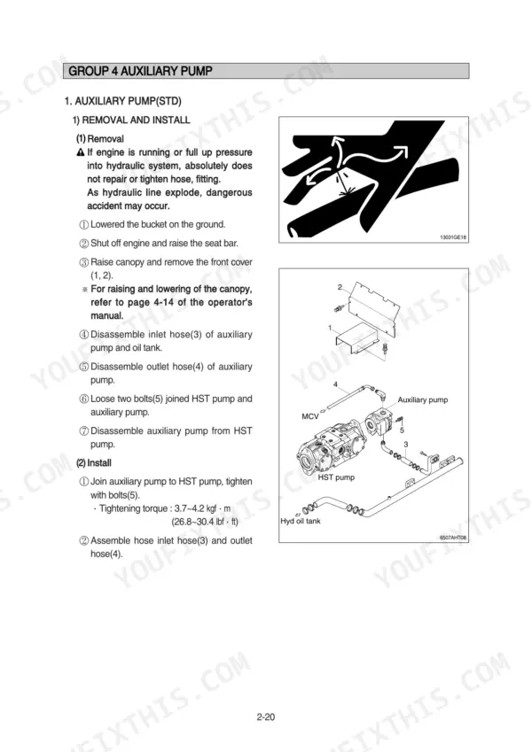
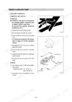
| Tightening torque for auxiliary pump bolts | 3.7~4.2 kgf·m (26.8~30.4 lbf·ft) | p. 42 |
| Tightening torque for front cover bolts | 14.3 kgf·m (103 lbf·ft) | p. 56 |
| Battery | MF90EH(300x172x203), CCA : 720A, 5HR : 72AH | p. 154 |
| Thermostat switch | On : 110°C, Off : Under 105°C | p. 154 |
| Engine Rated Gross Horsepower | 75.3 ps | p. 13 |
| Engine Oil Quantity | 11.2 L | p. 15 |
| Main Relief Valve Pressure | 175 kgf/cm2 | p. 14 |
| Auxiliary Pump Tightening Torque | 3.7-4.2 kgf·m | p. 42 |
Hyundai HSL850-7A Common Problems This Manual Covers
Hyundai HSL850-7A boom raises slowly, bucket action jerky, hydraulic power drops after machine warms up
Check hydraulic fluid level first, then test system pressure at the main relief valve; you should see 175 kgf/cm2 per the spec on page 14. If pressure reads low, adjust or replace the relief. Inspect boom cylinder seals for internal bypass and watch for leak down with the boom raised.
Manual Section: Boom and Bucket Hydraulic TroubleshootingLoader loses drive power on one side and will not travel straight
Start with the travel hydraulics procedures on page 173. Check hydraulic oil level and inspect both drive loops for leaks. Tighten any weeping flare fittings to spec; a size 8 fitting takes 5.1 to 6.3 kgf·m. If one side still drags, compare pressure readings side to side to isolate pump versus travel motor.
Manual Section: Travel Hydraulics Troubleshooting p. 173Engine cranks slowly or will not start in cold weather, glow plug lamp stays off
Load-test the battery before anything else; the factory unit is rated 720 CCA, spec on page 154. Charge or replace if it fails, then check glow plug circuit continuity at the plugs. Replace the fuel filter and bleed the system, since a half-plugged filter mimics a weak battery on cold mornings.
Manual Section: Electrical System p. 154Temperature gauge climbs fast under load, coolant overflow bottle boils after an hour of work
Check coolant level cold and inspect the radiator core; blow chaff out with compressed air from the fan side. Test the thermostat switch, which should close at 110°C and open below 105°C, spec on page 154. If the switch checks good, pull the water pump and inspect the impeller for erosion.
Manual Section: Electrical System p. 154Auxiliary hydraulics run attachments slowly, oil weeping around the auxiliary pump mounting flange
Wipe the pump flange dry, run the auxiliary circuit, and watch where fresh oil appears. Retorque the pump mounting bolts to 3.7 to 4.2 kgf·m following the service procedure on page 42; replace the flange O-ring if it still weeps. Verify coupler halves seat fully, since a half-seated coupler starves attachment flow.
Manual Section: Self Level Valve and Auxiliary Pump p. 42Frequently Asked Questions
How do I reset the boom/bucket function after starting the engine?
After starting the engine, you must momentarily press the reset switch to unlock the boom and bucket functions. The hydraulic system remains active until the seat bar is raised or the start switch is turned OFF. p. 149
What are the torque specifications for the auxiliary pump bolts?
The tightening torque for the bolts joining the auxiliary pump to the HST pump is 3.7 to 4.2 kgf·m (26.8 to 30.4 lbf·ft). p. 42
What is the recommended engine oil capacity for the HSL850-7A?
The engine oil capacity for the engine oil pan is 11.2 liters (2.9 U.S. gallons). p. 15
What is the required charge pressure for the HST pump?
The charge pressure relief valve is set to 260 psi (18 bar). The charge pressure must not be less than 220 psi (15.2 bar) for satisfactory operation. p. 64
What is the tightening torque for the boom cylinder gland?
The tightening torque for the boom cylinder gland is 60 ± 6 kgf·m (434 ± 43 lbf·ft). p. 134
How quickly can I access this Hyundai HSL850-7A manual after buying?
This is a 180-page searchable PDF ready for immediate download. Works on any device, so pull it up on your phone while you're under the hood. No shipping, no waiting.
Is this Hyundai HSL850-7A Service Manual printable?
Yes. Print a chapter or just the pages for the job at hand, for use in your own shop. Any home or office printer works.








Reviews
There are no reviews yet.