
Part of the John Deere Repair Manuals.
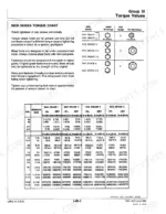
This 804-page John Deere 210C, 310C, 315C Backhoe Loader Repair Manual (OEM #TM-1420) puts axle, transmission, engine, and park brake service in your hands for every one of these three machines. Open it up and you get hydraulic schematics for the main pump, reservoir, oil cooler, and system relief valve, plus a torque section covering values you'd otherwise guess at and a full fluid capacities breakdown. Deep procedure coverage walks you through transmission teardown, steering cylinder rebuilds, and service brake hydraulics without skipping steps. Check the starter solenoid pull-in current at 13-15.5 amps and hold-in at 14.5-16.5 amps before you condemn a good part. No more pulling three different manuals because your backhoe's model number doesn't match the cover. Bookmarked by system, so you jump straight from cover to Park Brake without scrolling past 400 pages you don't need.
What's Inside This John Deere 210C, 310C, 315C Repair Manual
| System | Pages | Key Topics |
|---|---|---|
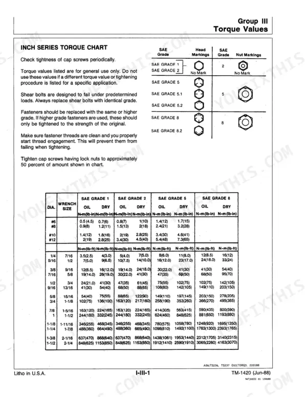
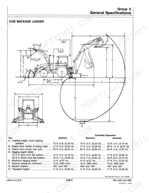
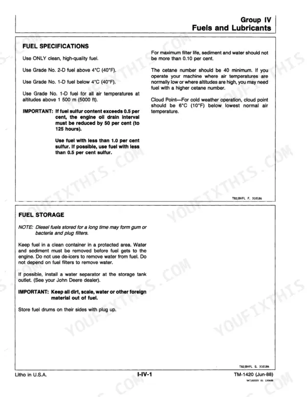
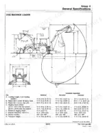
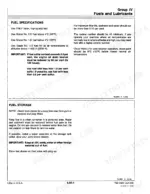
| General Information | 5-58 | Safety Information, General Specifications, Torque Values, Fuels and Lubricants, Inspection Procedure |
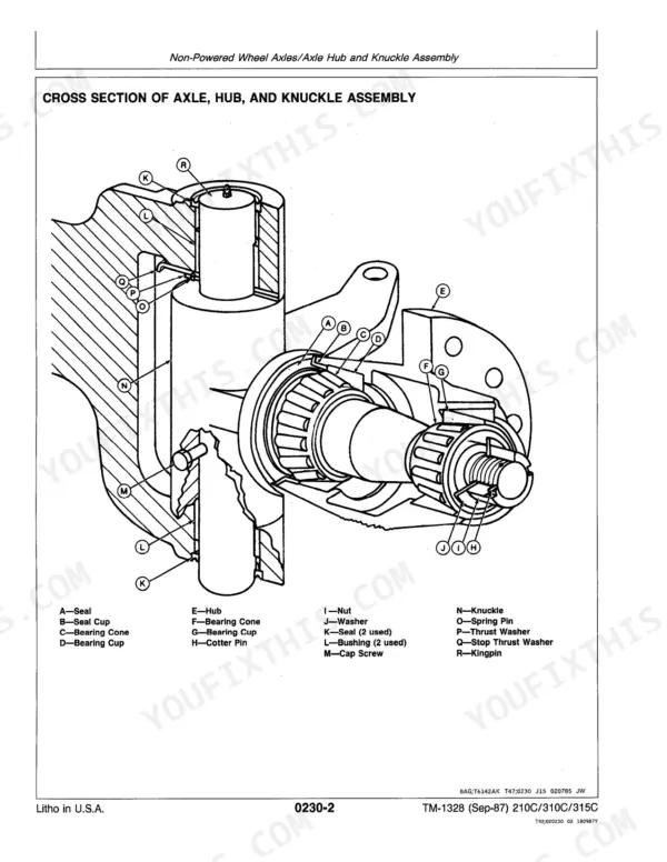
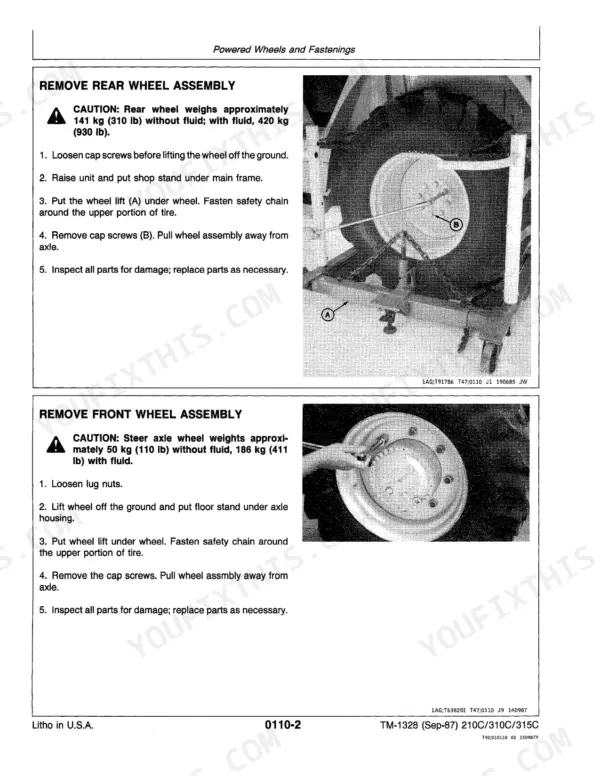
| Wheels | 59-72 | Powered Wheels and Fastenings, Non-Powered Wheels and Fastening |
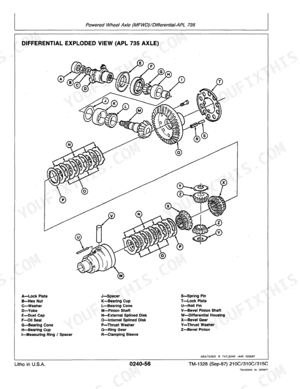
| Axles and Suspension Systems | 73-204 | Non-Powered Wheel Axles, Powered Wheel Axle (MFWD), Axle Shaft, Bearings, And Reduction Gears, Hydraulic System |
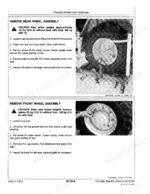
| Transmission | 205-316 | Removal and Installation, Gears, Shafts, Bearings, And Power Shift Clutch/Transaxle, Hydraulic System |
| Engine | 317-342 | Removal and Installation, Fuel Injection System |
| Engine Auxiliary Systems | 343-364 | Cold Weather Starting Aids, Cooling Systems, Speed Controls, Intake System, External Fuel Supply Systems |
| Torque Converter | 365-368 | Turbine, Gears, And Shafts |
| Steering System | 369-408 | Steering Relief Valve, Steering Cylinder, MFWD Steering Cylinder, Apl 1552 Axle, Apl 735 Axle |
| Service Brakes | 409-428 | Active Elements, Hydraulics |
| Park Brake & Control Linkage | 429-455 | Park Brake Active Elements, Brake Band Stop Screw and Lock Nut, Controls and Linkage Adjustment |
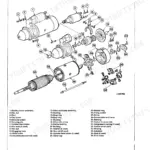
| Electrical System | 456-519 | Starting Motor Removal, Installation and Disassembly, Alternator and Regulator, Charging System Wiring, Wiring Harness, Switches, Motors and Actuators |
| Operator's Station | 520-569 | Operator Enclosure, Cab Removal and Installation, Seat and Seat Belt, Controls Layout, Heating and Ventilation |
| Hydraulic System, Controls and Valves | 570-654 | Control Valve Torque Specifications, Boom and Bucket Spools, Relief Valves, Pilot Controls, Hydraulic Pump |
| Loader and Backhoe Frames | 655-699 | Frame Removal and Installation, Control Linkage, Extendible Dipperstick Extension, Boom and Bucket Structures |
| Hydraulic Cylinders | 700-779 | Cylinder Removal, Rod and Piston Assembly, Seal Replacement, Boom, Bucket, Crowd and Swing Cylinders, Leak Testing |
| Hydraulic System, Attachments | 780-794 | Attachment Hydraulics, Auxiliary Circuits, Couplers |
| Dealer Fabricated Tools | 795-804 | Df Driver Tools for Bearings, Tool Dimensions and Fabrication Drawings |
Quick Reference Specifications
| Specification | Value | Page |
|---|---|---|
| All Models | ||
| Solenoid Pull-In Current | 13-15.5 amps | p. 495 |
| Solenoid Hold-In Current | 14.5-16.5 amps | p. 495 |
| Circuit Relief Valve Pressure Setting: A-Crowd in | 24 100 kPa (241 bar) (3500 psi) | p. 722 |
| 310C/315C | ||
| Spool End Screw (Bucket and Boom) Torque | 9-11 N·m (84-96 lb-in.) | p. 620 |
| Shoulder Screw (Bucket) Torque | 9-11 N·m (84-96 lb-in.) | p. 620 |
| 210C | ||
| Hydraulic Reservoir Capacity | 30 L | p. 320 |
| Axle Shaft Retaining Cap Screw Torque (APL 735 axle) | 163 ± 20 N·m | p. 172 |
| 310C, 315C | ||
| Axle Shaft Retaining Cap Screw Torque (APL 1552 axle) | 244 ± 8 N·m | p. 172 |
John Deere 210C, 310C, 315C Common Problems This Manual Covers
Starter cranks slow or intermittently, sometimes just clicks and won't turn the engine over
Bench test the starter solenoid: pull-in current should read 13-15.5 amps at 5.0 volts and hold-in current 14.5-16.5 amps at 10.0 volts, both per page 495. Also measure the R terminal contact height, which needs to sit at 1.52-2.29 mm (0.06-0.09 in.); a worn contact is what causes that intermittent click-no-crank symptom. Replace the solenoid if any reading falls outside spec.
Manual Section: Engine Auxiliary & Electrical System Repair p. 495Bucket or boom control spool binds or leaks after a valve rebuild, causing jerky lever response
Torque the spool end screw for bucket and boom to 9-11 N·m (84-96 lb-in.) as specified on page 620; overtightening here is what makes the spool bind in the bore. Set the shoulder screw and spool cap screws to the same 9-11 N·m, and torque the boom spool cap screws to 7 ± 0.7 N·m (5 ± 0.5 lb-ft). Cycle each spool by hand after assembly to confirm smooth travel before bolting the valve back on.
Manual Section: Hydraulic System Repair (Pumps, Valves, Cylinders) p. 620Frequently Asked Questions
What are the torque specifications for the John Deere 210C hydraulic pump mounting bolts?
The torque specification for the Sundstrand/Sauer hydraulic pump section cap screws and threaded studs (4 each) is 88–102 N·m (65–75 lb-ft). p. 570
How do you fix john Deere 210C backhoe loses all electrical power, no fan, wiper, or key-on functions?
Check the main power solenoid first; it is the usual culprit when everything on the machine goes dead at once. Pull the coil leads and test pull-in current, which should draw 13-15.5 amps as listed on page 495. Zero draw or an open reading means the solenoid is bad, so replace it. Also clean and re-torque the battery ground straps before condemning the ignition switch. p. 495
How do you fix hydraulic backhoe or loader functions unresponsive or significantly weak, bucket barely moves?
Tee a pressure gauge into the boom raise circuit and cycle the lever at operating RPM. Relief should build to 26 201 kPa (3800 psi) per the chart on page 722; if pressure hits spec but the cylinder still won't move, the cylinder seals are leaking internally. If pressure never climbs, check the reservoir suction screen for restriction before you condemn the main pump. p. 722
How do you fix engine cranks over but won't fire even though fuel is confirmed present at the tank?
Check the fuel shut-off solenoid on the injection pump; energized, it should click and pull the shutoff lever fully open. Probe for 12V at the connector with the key on. No voltage points to a wiring or ignition switch fault, while voltage with no click means the solenoid has failed and needs replacement. Bleed the fuel system afterward before attempting a restart.
Will this John Deere 210C Repair Manual download right away?
This is a 804-page searchable PDF ready for immediate download. Works on any device, so pull it up on your phone while you're under the hood. No shipping, no waiting.
Can I print a copy of this John Deere 210C Repair Manual for the shop?
Yes. Print the sections you need to take out to the shop for your own use. Standard letter or A4 paper works.
Are hydraulic diagrams part of this John Deere 210C Repair Manual?
Yes. The manual includes hydraulic circuit diagrams, system schematics, and component specifications with pressure ratings.







Reviews
There are no reviews yet.