
Part of the John Deere Repair Manuals.
All 846 pages of this John Deere 2500, 2500A and 2500E Professional Greens Mower technical manual PDF (OEM #TM1757) are built around one job: keeping these greens mowers cutting clean. Inside you get the full electrical section with wiring schematics, harness routing and circuit tests, complete hydraulic schematics for the mow and lift circuits, and separate teardown chapters for the gas and diesel engines. Work the interlock diagnostics when the engine cranks with the mow lever in TRANSPORT, or trace the reel circuit when the reels stop turning mid-round. Set crankshaft runout against the 0.05 mm (0.002 in.) service limit before you condemn a short block, and hold the cutting unit shield clearance at 1 mm (0.04 in.) after a reel rebuild. Guessing on a greens mower costs you a putting surface. Open this bookmarked file on your shop tablet and work from the factory numbers.
What's Inside This John Deere 2500, 2500A, 2500E Manual
| System | Pages | Key Topics |
|---|---|---|
| Safety | 5-10 | Safety-Alert Symbols and Signal Words, Handling Fluids Safely, Fire Prevention, Lifting Equipment, Emergency Preparedness |
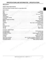
| Specifications and Information | 11-41 | General Vehicle Specifications, Gasoline and Diesel Engine Specifications, Steering and Hydraulic Specifications, Inch and Metric Fastener Torque Values, Identification Numbers, Machine Break-In |
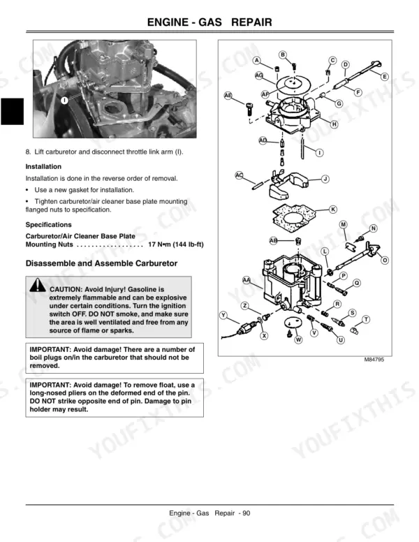
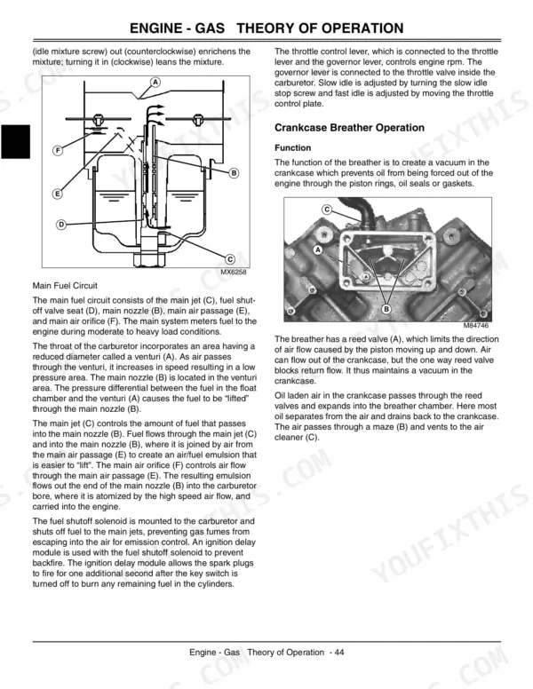
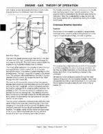
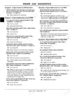
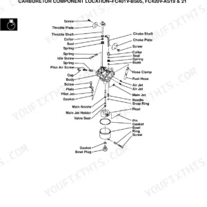
| Gas Engine | 42-146 | Component Location, Theory of Operation, Engine Troubleshooting, Compression and Cylinder Leakage Tests, Carburetor and Governor Adjustment, Starter and Charging Repair, Engine Removal, Disassembly and Installation |
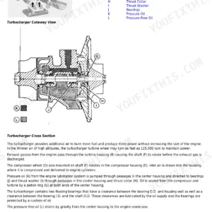
| Diesel Engine | 147-242 | Component Location, Theory of Operation, Diesel Engine Troubleshooting, Valve Lift and Injection Pump Timing, Fuel Injectors and Glow Plugs, Compression Test, Engine Removal, Disassembly and Installation |
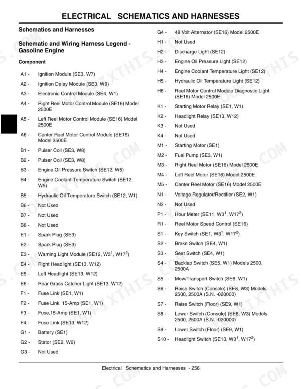
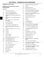
| Electrical, Schematics and Harnesses | 243-352 | System and Circuit Schematics, Wiring Harness Routing, Wire Colours, Sizes and Termination Points, Connector and Ground Locations |
| Electrical, Theory of Operation | 353-455 | Charging and Cranking Circuits, Fuel Shutoff Circuit, Safety Interlock and Mow Circuits, Warning Light and Gauge Circuits, Reel Drive Circuit Operation |
| Electrical, Diagnostics, Tests and Repair | 456-586 | Circuit Diagnostics, Component Tests (Switches, Relays, Solenoids, Sensors), Starter and Alternator Repair, Battery Service and Specifications |
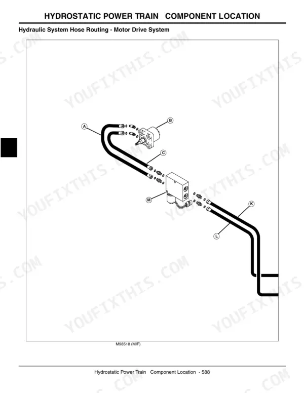
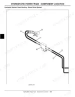
| Power Train | 587-638 | Hydrostatic Power Train Theory, Component Location, Traction and Third-Wheel-Assist Circuits, Test and Adjustment Specifications, Hydrostatic Pump and Wheel Motor Removal, Repair and Installation |
| Hydraulics | 639-718 | Hydraulic Schematics and Theory of Operation, Oil Filter and Expansion Tank, Lift Valve Assembly, Relief and Check Valves, Mow Circuit and lift/lower Circuit, Pressure Tests, Pump and Cylinder Repair |
| Steering | 719-750 | Steering Circuit Theory, Component Location, Test and Adjustment Specifications, Steering Valve and Cylinder Disassembly and Assembly, Steering Column Repair |
| Brakes | 751-764 | Brake System Component Location, Brake System Operation, Adjustment Specifications, Brake Linkage Adjustment, Brake Repair Specifications |
| Attachments | 765-822 | Cutting Unit Specifications, Cutting Unit Component Location, Reel and Bedknife Adjustment, Greens and Turf Conditioner (Gtc), Grass Catcher and Rollers, Disassembly, Inspection and Repair |
| Miscellaneous | 823-846 | Operator Protective Device (Opd) Removal and Installation, Rear Wheel Assist Disassembly and Assembly, Seat and Operator Station Repair, Repair Specifications |
Quick Reference Specifications
| Specification | Value | Page |
|---|---|---|
| Battery warm temperature | 16°C (60°F) | p. 6 |
| Crankshaft Runout (Service Limit) | 0.05 mm (0.002 in.) | p. 117 |
| Cutting Unit Shield Clearance | 1 mm (0.04 in.) | p. 784 |
John Deere 2500, 2500A, 2500E Common Problems This Manual Covers
John Deere 2500E reels stop spinning or fail to engage during mowing rounds
Check output voltage at the alternator with reels engaged; confirm at least 48V DC reaches the electric reel motors. Trace the circuit on the wiring diagram, , and verify pinout at the reel driver connector. Replace the alternator if voltage sags under load, or swap in a known-good reel motor to isolate a bad winding.
Manual Section: Wiring DiagramEngine dies unexpectedly after sitting, or is hard to restart after refueling
Remove the fuel cap and check for a hiss of vacuum release; a blocked vent starves the engine as fuel level drops. Clean or replace a restricted vent cap. Confirm tank capacity against the fluid chart, then follow the vent inspection interval on the maintenance schedule.
Manual Section: Maintenance IntervalsEngine starts when the park brake is released or mow lever is in TRANSPORT
Pull the seat, brake, and mow-lever interlock switches and test each for continuity to ground, following the troubleshooting procedures. A switch reading closed when it should be open lets the start circuit complete out of sequence. Check the interlock harness pinout and replace any switch that fails under load; do not bypass the circuit.
Manual Section: Troubleshooting ProceduresEngine does not stop within two seconds when operator leaves the seat with reels lowered
Test the seat switch and reel-lower interlock for continuity while cycling the seat and reel lift lever; per the troubleshooting procedures, shutdown must occur within two seconds. Trace suspect circuits on the wiring diagram, , and replace any switch or relay causing delay. Do not return the mower to service until shutdown time is verified.
Manual Section: Troubleshooting ProceduresBasket brackets pop out of the frame during turns or sudden bumps
Inspect the basket bracket retention tabs and frame slots for wear or deformation that lets the bracket walk free under load. Check cutting unit shield clearance against the 1 mm (0.04 in.) spec on page 784; a wider gap lets brackets shift during hard turns. Replace worn brackets or slotted frame hardware, and reseat baskets fully before locking each side.
Manual Section: Service Procedures p. 784Frequently Asked Questions
What are the recommended service intervals?
For the diesel engine, the cooling system should be drained and refilled with fresh coolant mixture every 36 months or 3,000 hours when using John Deere Pre-Diluted coolants. Bio HY-GARD hydrostatic transmission and hydraulic oil should be changed every 400 hours or annually. Backlapping cutting units should be performed on a routine basis approximately every 25 hours. p. 27
What fluids and capacities does this machine require?
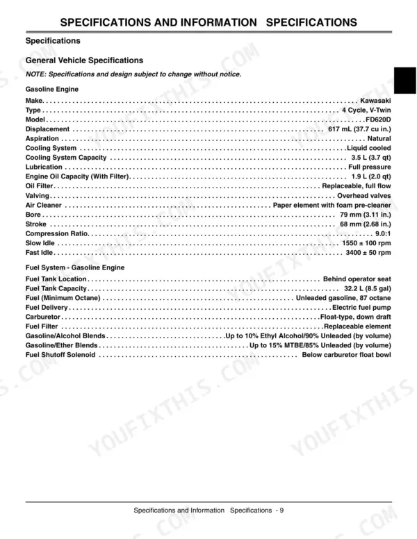
For the gasoline engine, the engine oil capacity with filter is 1.9 L (2.0 qt) and the cooling system capacity is 3.5 L (3.7 qt). The fuel tank capacity for both gasoline and diesel models is 32.2 L (8.5 gal). For hydraulics, the reservoir oil capacity is 20.4 L (5.4 gal) and the total system oil capacity is 28.8 L (7.6 gal). p. 13
How to troubleshoot engine won't start?
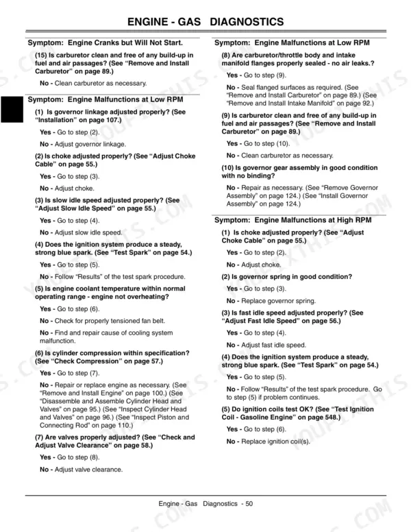
To troubleshoot an engine that cranks but will not start, first check if the battery voltage is within 11.8-13.2 volts. Next, verify that the choke is adjusted properly and that the fuel in the tank is fresh, clean, and of the proper grade. For a complete diagnostic tree, refer to page 53 for gasoline engines or page 147 for diesel engines. p. 53
What are the valve clearance specifications?
For the gasoline engine, both intake and exhaust valve clearance should be 0.25 mm (0.01 in.). For the diesel engine, the valve clearance is 0.2 mm (0.008 in.). p. 37
What torque specifications are listed?
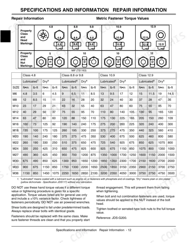
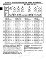
The manual provides extensive torque specifications. For example, M6 metric fasteners (Class 4.8) require 4.8 N•m (3.5 lb-ft) when lubricated, while M6 metric fasteners (Class 8.8 or 9.8) require 9 N•m (6.5 lb-ft) when lubricated. Inch fastener torque values are also provided, such as 1/4 inch (Grade 1) requiring 3.7 N•m (2.8 lb-ft) when lubricated. Refer to pages 16-20 for detailed metric and inch fastener torque values, and pages 37 and 140 for engine-specific torque specifications. p. 16
Is this John Deere 2500 manual a PDF I download?
Immediate download of the complete 846-page searchable Technical Manual. Access it on any device, from a laptop at your desk to a phone in the field.
Is this John Deere 2500 Technical Manual printable?
No restrictions at all. Print individual pages, full chapters, or the entire manual. The PDF is completely unlocked.







