Part of the John Deere Repair Manuals.
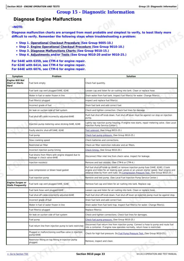
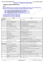
Need to diagnose a 4WD loader? All 676 pages of this John Deere 544E operation and test manual, diagnostic pdf (OEM #TM1413) focus on one thing: getting your 544E, 544E LL, 544E TC, 624E, and 644E back to factory condition. You get complete electrical wiring diagrams, main hydraulic system schematics, and extensive step-by-step diagnostic charts for the engine and power train. Open to the troubleshooting sections to trace down everything from differential lock failures to secondary steering faults. Confirm the 544E lube pressure is sitting between 20.7 and 103 kPa, then verify your injection pump lever override at slow idle is adjusted to exactly 2-4 mm. Stop tearing your hair out over undocumented faults. Download this bookmarked file, search by keyword to locate the exact spec, and fix your machine.
What's Inside This John Deere 544E to 644E Loaders Manual
| System | Pages | Key Topics |
|---|---|---|
| General Information | 7-55 | Group 01 - Safety Information (Handle Fluids Safely-Avoid Fires, Prevent Battery Explosions, Prepare for Emergencies, Prevent Acid Burns, Handle Chemical Products Safely, Avoid High-Pressure Fluids, Park Machine Safely, Support Machine Properly, Wear Protective Clothing, Work in Clean Area, Service Machines Safely, Work in Ventilated Area, Illuminate Work Area Safely, Replace Safety Signs, Use Proper Lifting Equipment, Remove Paint Before Welding or Heating, Avoid Heating Near Pressurized Fluid Lines, Keep ROPS Installed Properly, Service Tires Safely, Avoid Harmful Asbestos Dust, Practice Safe Maintenance, Use Proper Tools, Dispose of Waste Properly, Live with Safety) |
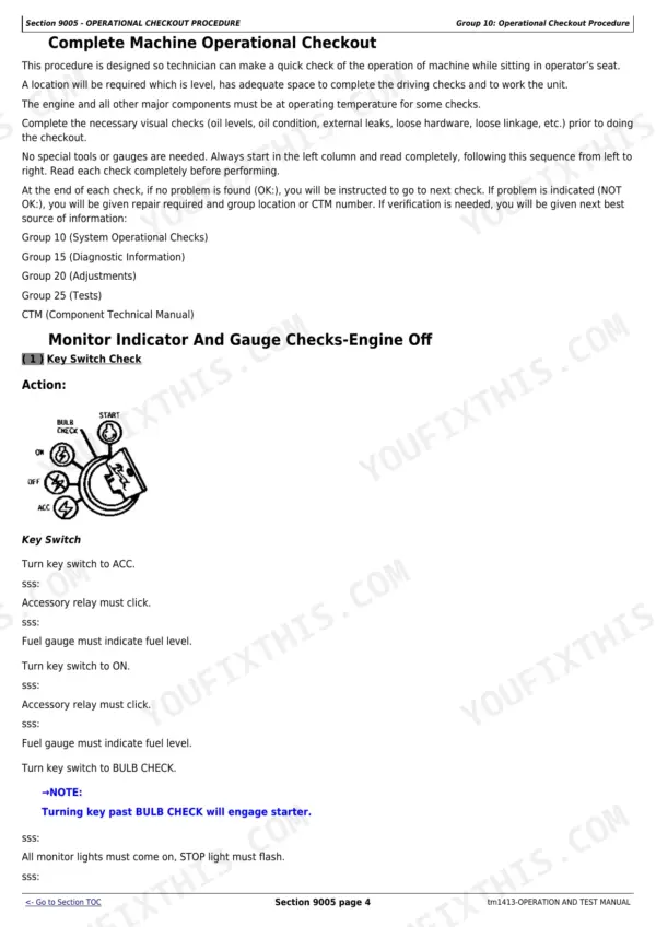
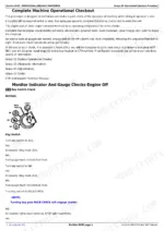
| Operational Checkout Procedure | 56-101 | Group 10 - Operational Checkout Procedure (Operational Checkout Record Sheet-544E, 624E, And 644E, Cab Component and Vandal Protection Checks) |
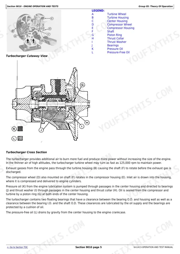
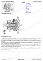
| Engine Operation and Tests | 102-183 | Group 05 - Theory of Operation (Cooling System Operation-544E, 624E, Cooling System Operation-644E, Thermostat Operation, Air Cleaner Operation, Turbocharger Operation, Engine Lubrication-544E, Engine Lubrication Operation-644E, Fuel System Operation-544E, Fuel System Operation-644E, Fuel Supply Pump Operation-544E, Fuel Pump Operation-644E, Fuel Filter Operation, Fuel Injection Pump Operation-544E, Fuel Injection Pump Operation-644E, Fuel Injection Nozzle Operation-544E, Fuel Injection Nozzle Operation-644E) |
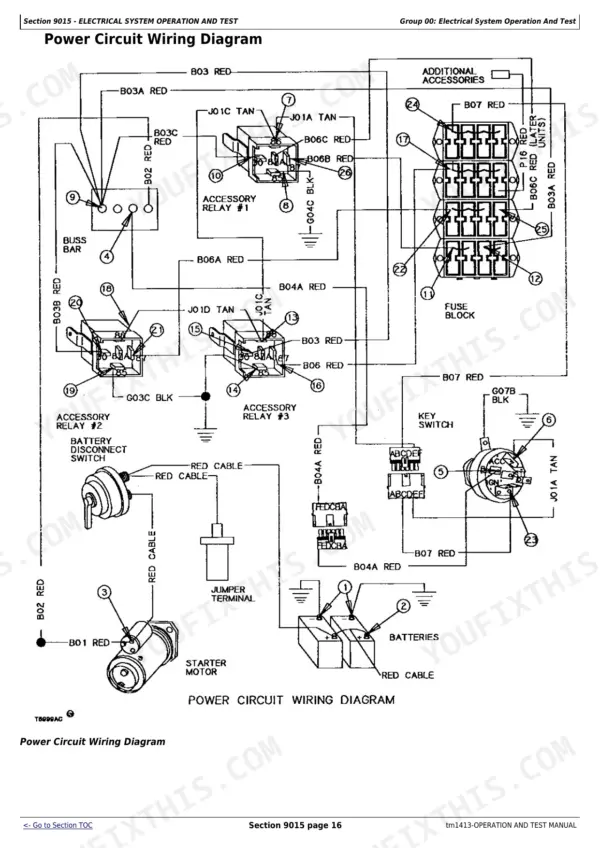
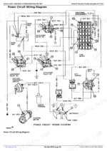
| Electrical System Operation and Test | 184-342 | Group 00 - Electrical System Operation and Test (Safety Precautions, Using Booster Batteries-12 Volt System, Visually Inspect Electrical System, Testing the Electrical System, Common Circuit Test, Electrical Operational Checks, Electrical Schematic Symbols, Wiring Diagram Information, Battery-Diagnose Malfunctions, Battery Operation, Battery Specifications, Fuse Specifications, Bulb Replacement Specifications, Power Circuit Operational Checks, Power Circuit Operation, Power Circuit Wiring Diagram, Power Circuit Test, Diagnose Starter Circuit Malfunctions, Diagnose Fuel Shut-Off Malfunctions-544E, 624E, Starting Circuit and Fuel Shut-Off Solenoid Operational Checks, Starting Circuit and Fuel Shut-Off Solenoid Operation, Starter Operation, Start Circuit and Fuel Shut-Off Solenoid Wiring Diagram, Start Circuit and Fuel Shut-Off Solenoid Tests, Charging Circuit Operational Checks-65 Amp Alternator, Alternator Operation-65 Amp Motorola, Charging Circuit Operation-65 Amp Motorola Alternator-, Charging Circuit Wiring Diagram-65 Amp Motorola-, Charging Circuit Operational Checks-90 Amp and 105 Amp Alternator, Alternator Operation-90 Amp and 105 Amp Delco Remy, Charging Circuit Operation-105 Amp Delco-Remy Alternator-, Charging Circuit Wiring Diagram-105 Amp Alternator-, Charging Circuit Operation-90 Amp Delco-Remy Alternator, Charging Circuit Wiring Diagram-90 Amp Delco-Remy Alternator, Charging Circuit Operational Checks-130 Amp Alternator, Alternator Operation-130 Amp Motorola, Charging Circuit Operation-130 Amp Motorola Alternator, Charging Circuit Wiring Diagram-130 Amp Motorola Alternator, Amp Alternator Voltage Adjustment, Diagnose Logic Module and Warning Alarm Circuit Malfunctions, Logic Module and Warning Alarm Circuit Operation, Logic Module and Warning Alarm Wiring Diagram, Logic Module Test in Machine, Logic Module Bench Test, Indicator Circuit Operational Checks-Top Row, Indicator Circuits Operation-Top Row, Indicator Circuits Wiring Diagram-Top Row, Indicator Circuit Operational Checks-Middle Row, Indicator Circuits Operation-Middle Row, Indicator Circuits Wiring Diagram, Park Brake Switch Adjustment, Pressure Switch and Sender Test, Gauges and Horn Circuit Operational Checks, Gauges and Horn Circuits Operation, Gauges and Horn Circuit Wiring Diagram, Return-To-Dig and Boom Kickout Circuit Operational Checks, Return-To-Dig and Boom Height Kickout Circuit Operation, Return-To-Dig and Boom Height Kickout Wiring Diagram, Boom Height Kickout Adjustment, Return-To-Dig Adjustment, Start Aid, Reverse Warning Alarm, And Cigar Lighter Operational Checks, And Cigar Lighter Circuit Operation, And Cigar Lighter Circuit Operation Wiring Diagram, Secondary Steering Circuit Operational Checks, Secondary Steering Circuit Operation, Secondary Steering Wiring Diagram, Secondary Steering Circuit Test, Secondary Steering Controller Test, Secondary Steering Pressure Switch, Hour Meter Circuit Operational Checks, Hour Meter Circuit Operation, Hour Meter Circuit Wiring Diagram, Boom Down Relay Circuit Operational Checks, Boom Down Circuit Operation-, Boom Down Circuit Wiring Diagram-, Differential Lock and Clutch Cut-Off Circuit Operational Checks, Differential Lock and Clutch Cut-Off Circuit Operation, Differential Lock and Clutch Cut-Off Circuits Wiring Diagram, Turn Signal and Flasher Circuit Operational Checks, Turn Signal and Flasher Indicator Circuit Operation, Turn Signal and Flasher Indicator Circuit Wiring Diagram, Drive, Work, Brake and Gauge Light Circuit Operational Checks, Brake and Gauge Light Circuit Operation, Brake and Gauge Light Circuits Wiring Diagram, Windshield Wiper and Washer Circuit Checks, Windshield Wiper and Washer Circuit Operation, Windshield Wiper/Washer Circuit Wiring Diagram, Pin Disconnect Circuit Checks-544E Tc, Pin Disconnect Circuit Operation, Pin Disconnect Circuit Wiring Diagram, Radio Circuit Operation, Electrical Component Location Drawing) |
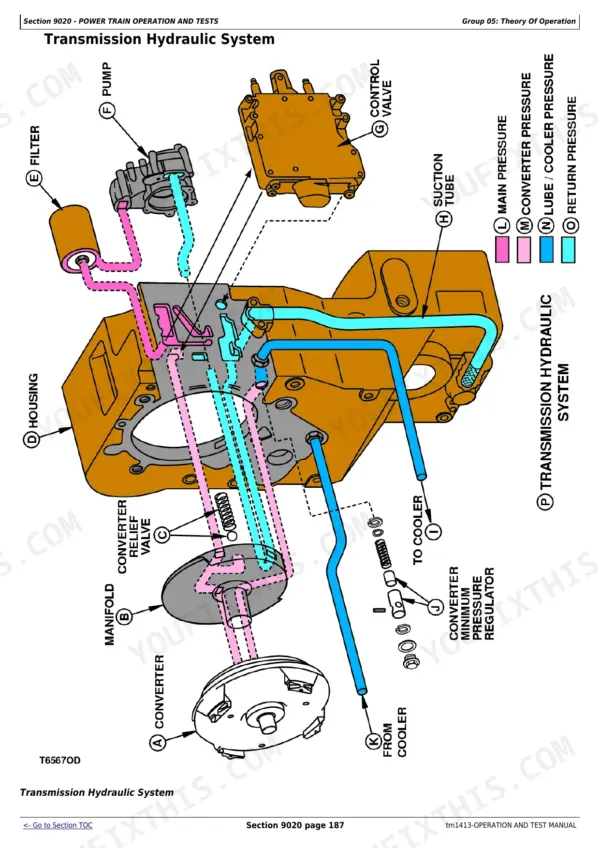
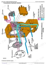
| Power Train Operation and Tests | 343-492 | Group 05 - Theory of Operation (Power Train Component Overview, Drive Dampener, Transmission Clutch Engagement, Torque Converter Operation, Transmission Operation-Neutral, Transmission Operation-1st Gear Forward, Transmission Operation-2nd Gear Forward, Transmission Operation-3rd Gear Forward, Transmission Operation-4th Gear Forward, Transmission Operation-1st Gear Reverse, Transmission Operation-2nd Gear Reverse, Transmission Operation-3rd Gear Reverse, Clutch Operation, Transmission Hydraulic Components, Transmission Hydraulic System, Transmission Pump Operation, Transmission Control Valve Components, Transmission Control Valve-1st Gear Neutral, Transmission Control Valve-4th Gear Forward, Shift Modulation, Shift Modulation-1st Gear, Shift Modulation-2nd, 3rd, And 4th Gears, Thermal Bypass Valve Operation, Differential Lock Operation, Final Drive Operation, Axle Outer Seal and Bearing Operation, Axle Disconnect Operation, Brake Hydraulic System, Brake Pump Operation, Accumulator Operation, Brake Valve Operation, Wet Chambered Brake Valve, Pressure Reducing Valve Operation-Neutral, Pressure Reducing Valve Operation-Differential Lock on) |
| Hydraulic System Operation and Test | 493-613 | Group 05 - Theory of Operation (Steering Circuit Component Location, Steering Circuit Components, Steering Circuit Operation-Right Turn, Main Hydraulic Pump Operation, Priority Valve Operation, Steering Valve Operation, Crossover Relief Valve Operation, Steering Cylinder Operation, Steering Accumulator Operation-644E Later Units, Secondary Steering System Operation, Inlet Manifold Operation, Loader Hydraulic System, Pressure Reducing Valve-Secondary Boom Lower Operation, Pilot Controller Operation, Boom Section Operation, Bucket Section Orifice Check Valve, Bucket Section Operation-544E, 624E, And 644E, Bucket Section Operation-544E Tc and 544E Ll, Auxiliary Section Operation, System Relief Valve Operation, Circuit Relief Valve Operation, Anti-Cavitation Valve Operation, Loader Cylinder Design, Return Filter Operation, Pin Disconnect Circuit Operation-544E Tc) |
| Heating and Air Conditioning System Operation and Tests | 614-676 | Group 05 - Theory of Operation (Refrigerant System, Electrical System Wiring Diagram-Early Machines, Electrical System Schematic-Early Machines, Electrical System Wiring Diagram-Later Machines, Electrical System Schematic-Later Machines, Receiver-Dryer Operation, Expansion Valve Operation, Thermostat Control Switch Operation, Compressor Relief Valve Operation) |
Documents This Manual Refers To
The manufacturer cites these publications by number. We carry them:
Quick Reference Specifications
| Specification | Value | Page |
|---|---|---|
| 544E | ||
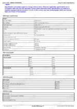
| Transmission case and filter | 9.5 L | p. 24 |
| 544E Lube Pressure | 20.7-103 kPa (0.2-1.0 bar) (3-15 psi) | p. 452 |
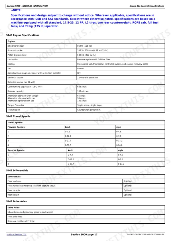
| 544E Cooling system capacity | 23.5 L | p. 24 |
| 544E, 624E | ||
| 544E and 624E Injection Pump Lever Override at Slow Idle Position | 2-4 mm (0.08-0.16 in.) | p. 164 |
| 624E | ||
| 624E Lube Pressure | 28-172 kPa (0.3-1.7 bar) (4-25 psi) | p. 452 |
| All Models | ||
| 544E Hydraulic Reservoir Capacity | 76 L (20 gal) | p. 557 |
| Magnet-to-Boom Height Kickout Switch Clearance | 9 ± 3 mm (0.35 ± 0.12 in.) | p. 560 |
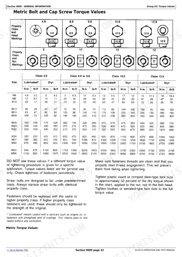
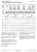
| ROPS Mounting Bolts Torque | 620 ± 120 N·m (457 ± 88 lb-ft) | p. 38 |
| 644E | ||
| 644E Fuel tank capacity | 284 L | p. 37 |
John Deere 544E to 644E Loaders Common Problems This Manual Covers
John Deere 544E transmission shifts late across every gear, forward and reverse, but never slips once engaged
Check the Power Train System Malfunctions Diagnosis chart for shift linkage binding versus low transmission pressure. Pull a fluid sample; frothy or milky oil points to aeration or coolant contamination, not the linkage. Confirm oil temperature holds at 65 ± 6°C (150 ± 10°F) per page 452 before condemning the valve body.
Manual Section: Power Train System Malfunctions DiagnosisLoader won't move at all after sitting parked overnight, engine runs fine
Check the Power Train System Malfunctions Diagnosis section for torque converter drain-down and scavenger pump screen blockage. Remove and clean the scavenger screen if oil doesn't refill the converter housing on startup. Verify converter relief valve pressure reads 850-1050 kPa (125-155 psi) per page 454 before replacing the torque converter charging pump.
Manual Section: Power Train System Malfunctions DiagnosisBucket won't dump fully or curl all the way, cylinder feels sluggish under load
Run the hydraulic warm-up procedure on page 531 (cycle all functions until the reservoir is uncomfortable to hold a hand against, about 50°C/120°F) before condemning any valve. Check the bucket dump circuit relief per page 533; the bucket must not roll back under load. Check hydraulic oil level and run the leakage test referenced on page 545 if cylinders drift.
Manual Section: Hydraulic System Malfunctions Diagnosis p. 531Engine cranks slowly or won't turn over at all when temperatures drop below freezing
Check the Diagnose Engine Malfunctions troubleshooting chart for hard-start conditions. Verify battery cold cranking capacity meets 925 amps (644E) per page 36 and test the starter circuit per the checks beginning if the solenoid clicks but the engine won't turn. Inspect the glow plug or ether start aid before pulling the starter.
Manual Section: Diagnose Engine MalfunctionsBoom height kickout won't engage at the right point, bucket rolls back too early or late
Measure the magnet-to-boom height kickout switch clearance; spec is 9 ± 3 mm (0.35 ± 0.12 in.) per page 560. Adjust the switch bracket until clearance falls within tolerance, then cycle the boom to confirm consistent kickout. Check wiring at the indicator circuits per if the switch measures correctly but kickout still won't trigger.
Manual Section: Boom Height Kickout Adjustment p. 560Frequently Asked Questions
How to adjust John Deere 544E joystick calibration?
The manual describes adjusting the pilot control valve for lever travel and feel positions. To adjust lever travel, add or remove spool positioning shims (A). To adjust pressure for feel positions and 3/4 lever travel, add or remove spool metering shims (B). Shims are available in sizes such as 0.004 in., 0.007 in., and 0.015 in. p. 604
What are the fluid and filter replacement specifications for the John Deere 544E transmission?
For the John Deere 544E, the transmission case and filter capacity is 9.5 L (10 qt). The recommended transmission oil is JOHN DEERE HY-GARD TRANSMISSION AND HYDRAULIC OIL, which is formulated to provide optimum clutch engagement and maximum protection against mechanical wear. p. 51
What is the engine oil capacity for the John Deere 544E, including the filter?
For the John Deere 544E, the engine crankcase and filter capacity is 19 L (20 qt). This specification is found in the drain and refill capacities chart for the 544E model. p. 24
What is the cooling system capacity for the John Deere 544E?
The cooling system capacity for the John Deere 544E is 23.5 L (25 qt). This information is listed under the drain and refill capacities for the 544E model. p. 24
How will I receive this John Deere 544E & variants manual?
Immediate download of the complete 676-page searchable Operation and Test Manual, Diagnostic. Access it on any device, from a laptop at your desk to a phone in the field.
Can I print pages of this John Deere 544E & variants manual for my own shop?
Yes. Print the pages or sections you need for your own shop use. Any standard printer works.
Can I find wiring schematics in this John Deere 544E & variants manual?
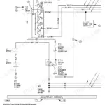
Yes, this John Deere 544E & variants Operation and Test Manual, Diagnostic includes complete electrical wiring diagrams, wire routing, and connector pinouts.