Part of the John Deere Repair Manuals.
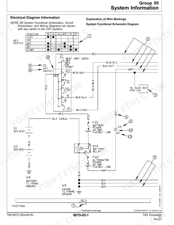
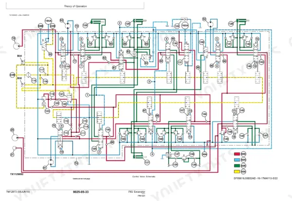
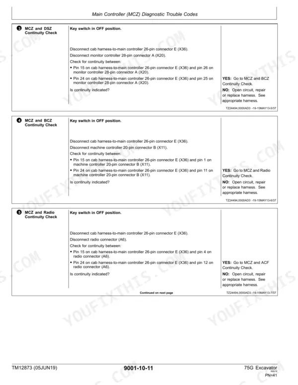
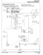
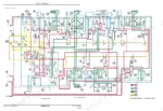
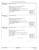
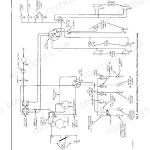
TM12873 settles how the John Deere 75G excavator is diagnosed, tested and checked out, in 792 pages of factory technical documentation. As a John Deere 75G technical manual PDF, it lays out wiring diagrams for the electrical sub-systems and hydraulic schematics that show the circuit routing behind each Hydraulic System test. Trouble codes are grouped by controller: main controller (MCZ), engine control unit (ECU), monitor controller (DSZ) and air conditioner controller (ACF), so you can match a code to its source. Swing bearing play should read 0.2 to 1.0 mm, with 2.0 to 3.05 mm the maximum allowable. Torque the 100-pin X3 harness connector to 10 N·m (89 lb.-in.). When your job is the full operational checkout, that procedure sits in its own section ahead of the Engine section. Bookmarks and a searchable text layer take you from a code or component name straight to the page that covers it.
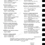
What's Inside This Manual
| System | Pages | Key Topics |
|---|---|---|
| General Information | 1-22 | Safety |
| Diagnostics | 23-154 | Main Controller Diagnostic Trouble Codes, Engine Control Unit Diagnostic Trouble Codes, Monitor Controller Diagnostic Trouble Codes |
| Operational Checkout Procedure | 155-200 | Operational Checkout |
| Engine | 201-216 | Theory of Operation, Diagnostic Information, Adjustments, Tests |
| Electrical System | 217-514 | System Information, System Diagrams, Sub-System Diagnostics, Monitor Operation, References |
| Power Train | 515-524 | Theory of Operation, Diagnostic Information |
| Hydraulic System | 525-756 | Theory of Operation, Diagnostic Information, Tests |
| Heating and Air Conditioning | 757-792 | Theory of Operation, Diagnostic Information, Tests |
Quick Reference Specifications
| Specification | Value | Page |
|---|---|---|
| Cab Harness-to-Machine Harness 100-Pin Connector (X3) Torque | 10 N·m (89 lb.-in.) | p. 158 |
| Swing Bearing Play (normal) | 0.2—1.0 mm (0.008—0.039 in.) | p. 524 |
| Swing Bearing Play (maximum allowable) | 2.0—3.05 mm (0.079—0.12 in.) | p. 524 |
| Hydraulic Oil Temperature | 45—55°C (110—130°F) | p. 723 |
| 100-Pin Connector (X3) Torque | 10 N·m (89 lb-in) | p. 31 |
| Cooling Water Temperature Sensor Abnormal High (Overheat) Threshold | 110°C (230°F) | p. 103 |
| Fuel Temperature Sensor Abnormal High Threshold | 90°C (194°F) | p. 106 |
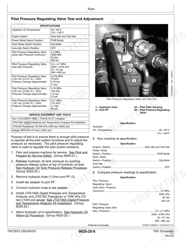
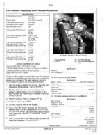
| Pilot Pressure Regulating Valve (slow idle) Pressure (minimum) | 3.0 MPa (3000 kPa, 30 bar, 435 psi) | p. 724 |
| Pilot Pressure Regulating Valve (fast idle) Pressure | 3.2—4.7 MPa (3200—4700 kPa, 32—47 bar, 464—682 psi) | p. 724 |
| Control Valve Spool Actuating Pressure | 3.4—4.0 MPa (3400—4000 kPa, 34.0—40.0 bar, 493—580 psi) | p. 726 |
| Travel Speed Solenoid Valve (port SI) Pressure | Monitoring Device Reading ± 0.2 MPa (± 200 kPa, ± 2.0 bar, ± 29.0 psi) | p. 727 |
| Pump 1 and Pump 2 Main Relief Valve (Travel Adjustment) Pressure | 31.6—33.6 MPa (31 600—33 600 kPa, 316.0—336.0 bar, 4583—4873 psi) | p. 731 |