


Part of the John Deere Repair Manuals.
This is the shop-floor repair manual for the 2012-2016 John Deere 9R articulated tractors: 9360R, 9410R, 9460R, 9510R and 9560R, with both the PowerTech 9.0 L and 13.5 L engines. It is a teardown and rebuild book, not a diagnostic one: engine removal, fuel and cooling service, the 18-speed Power Shift and the Mechanical Shift transmission down to clutch packs and wear limits, single and double reduction axles, steering, brakes, hydraulics, the cab, and the hinge and gudgeon articulation joint that makes these tractors what they are. Torques, pressures, spring lengths and reusability limits are printed where you need them. The wiring group covers harness routing and replacement for every option and region.
What's Inside This John Deere 9R Series (9360R-9560R) Repair Manual
| System | Pages | Key Topics |
|---|---|---|
| General Information (Section 10) | 9-79 | Safety and General Information: Dealer Predelivery, Specifications and General References |
| Engine (Section 20) | 80-105 | Engine Removal and Installation for Both the 9.0 L and 13.5 L Engines, Mounts, Dampers and Drive Couplers |
| Fuel and Cooling Systems (Section 30) | 106-297 | Fuel and Cooling Systems: Tanks, Filters, Pumps, Air Intake, Turbocharger Plumbing, Radiator, Thermostats, Deaeration and Oil Coolers |
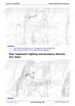
| Electrical (Section 40) | 298-598 | Electrical: Starting and Charging, Batteries, Wiring Harness Routings for Every Option (by Region NA/Eur, By Engine 9L / 13.5L / PowerTech, By Transmission MST/PST, By Axle, Plus AutoTrac, JDLink, Autoload and Cab Harnesses) |
| Speed Power Shift Transmission (Section 50) | 599-650 | 18-Speed Power Shift Transmission (PST) Service |
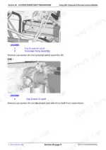
| Mechanical Shift Transmission (MST) (Section 55) | 651-887 | Mechanical Shift Transmission (MST): Control Valve, Pumps, Clutch Packs, Brake Pistons and Wear Limits |
| Drive Systems (Section 56) | 888-952 | Drive Systems: Drive Shafts, PTO and Differential Drive |
| Single Reduction Axles (Section 57) | 953-1069 | Single Reduction Axles: Housings, Planetaries and Wheel Ends |
| Double Reduction Axles (Section 58) | 1070-1184 | Double Reduction Axles: Housings, Planetaries and Wheel Ends |
| Steering and Brakes (Section 60) | 1185-1285 | Steering and Brakes: Steering Valve and Column, Priority Valve, Steering Enable Spool and Solenoids, AutoTrac Valve, Brakes |
| Hydraulics (Section 70) | 1286-1423 | Hydraulics: Hydraulic and Axle Pumps, Pump Controller, Reservoir, Valves and Plumbing |
| Miscellaneous (Section 80) | 1424-1471 | Miscellaneous Service Information |
| Operator Station (Section 90) | 1472-1669 | Operator Station: Cab, Seat, Armrest Controls, HVAC and Roof |
| Hinge and Gudgeon (Section 95) | 1670-1731 | Hinge and Gudgeon: the Articulation Joint of the Tractor, Bearings and Pins |
| Dealer Tools (Section 99) | 1732-1817 | Dealer-Fabricated Tools and Tap-Out Harnesses |
Quick Reference Specifications
| Specification | Value | Page |
|---|---|---|
| 9.0 L engine | ||
| Engine mount-to-frame cap screw torque | 325 N.m (240 lb-ft) | p. 81 |
| 13.5 L engine | ||
| Engine mount-to-frame cap screw torque | 325 N.m (240 lb-ft) | p. 101 |
| Engine lift bracket cap screw torque | 90 N.m (66 lb-ft) | p. 98 |
| Damper-to-flywheel cap screw torque | 101 N.m (75 lb-ft) | p. 101 |
| MST transmission | ||
| Clutch plate thickness (wear limit) | 6.87 - 7.13 mm (0.270 - 0.280 in.), flatness 0.3 mm (0.012 in.) | p. 795 |
| Brake piston clutch plate thickness | 4.70 - 4.86 mm (0.185 - 0.191 in.) | p. 760 |
| Pressure regulating valve spring | free length 126 mm (4.96 in.), test length 100 mm | p. 716 |
| Pump idler gear shaft OD (wear check) | 19.46 mm (0.766 in.) | p. 726 |
| All models | ||
| Steering enable spool valve spring | free length 44.45 mm (1.75 in.), test length 37 mm | p. 1216 |
| Steering enable solenoid torque | 52 N.m (38 lb-ft) | p. 1216 |
| Load sense blocking valve torque | 40 N.m (30 lb-ft) | p. 1217 |
| Priority valve mounting cap screw torque | 125 N.m (92 lb-ft) | p. 1220 |
| AutoTrac valve mounting cap screw torque | 35 N.m (26 lb-ft) | p. 1214 |
| Steering wheel nut torque | 30 N.m (22 lb-ft) | p. 1185 |
| Steering valve body cap screw initial torque | 24 N.m (212 lb-in.) | p. 1212 |
| Hydraulic pump-to-pump mounting cap screw torque | 125 N.m (92 lb-ft) | p. 1286 |
| Hydraulic pump-to-transmission cap screw torque | 125 N.m (92 lb-ft) | p. 1287 |
| Pump controller-to-hydraulic pump socket head screw torque | 14 N.m (120 lb-in.) | p. 1319 |
| Hydraulic reservoir retaining cap screw torque | 90 N.m (66 lb-ft) | p. 1298 |
| Starting motor current draw | 450 A at 11.1 V | p. 482 |
| Radiator pressure test | 90 kPa (0.9 bar) (13 psi) | p. 161 |
| Deaeration cap pressure test | 103 kPa (1.03 bar) (15 psi) | p. 162 |
| Oil cooler leak test air pressure | 700 - 1000 kPa (7 - 10 bar) (100 - 150 psi) | p. 267 |
| Fuel tank support-to-frame cap screw torque | 128 N.m (95 lb-ft) | p. 106 |
| Air intake flange clamp / coupling hose clamp torque | 20 N.m (178 lb-in.) / 10 N.m (88 lb-in.) | p. 114 |
| Thermostat cover cap screw torque | 73 N.m (54 lb-ft) | p. 135 |
John Deere 9R Series (9360R-9560R) Common Problems This Manual Covers
MST transmission slipping or losing drive under load
Section 55 tears the Mechanical Shift Transmission down to the control valve, pumps, clutch packs and brake pistons. Measure plates against the printed limits: clutch plate 6.87 - 7.13 mm with 0.3 mm flatness, brake piston plates 4.70 - 4.86 mm, pressure regulating valve spring free length 126 mm, pump idler gear shaft 19.46 mm. The numbers tell you what is reusable and what gets replaced.
Manual Section: Mechanical Shift Transmission (MST) (Section 55) p. 795Overheating or coolant loss on the 9.0 L or 13.5 L engine
Section 30 covers the whole cooling circuit: radiator, thermostats, deaeration system and oil coolers. It gives the test values that separate a bad part from a bad guess: radiator pressure test at 90 kPa (13 psi), deaeration cap at 103 kPa (15 psi), oil cooler leak test at 700 - 1000 kPa air, thermostat cover screws torqued to 73 N.m.
Manual Section: Fuel And Cooling Systems (Section 30) p. 161Slow or no crank, suspected starting and charging trouble
Section 40 covers starting and charging service and batteries, with the benchmark that matters: starting motor current draw of 450 A at 11.1 V. It also carries harness routing drawings named per option and region, so a chafed or rodent-eaten harness can be identified and replaced. For circuit schematics and fault codes, pair it with the diagnostic manual.
Manual Section: Electrical (Section 40)Wandering steering or AutoTrac hardware service
Section 60 services the steering valve and column, priority valve, steering enable spool and solenoids, AutoTrac valve and brakes. Real assembly numbers throughout: steering enable spool spring free length 44.45 mm, enable solenoid at 52 N.m, priority valve mounting screws at 125 N.m, AutoTrac valve mounting at 35 N.m, steering valve body screws at 24 N.m initial.
Manual Section: Steering And Brakes (Section 60) p. 1670Frequently Asked Questions
Can I use this manual to read fault codes or reset a warning light on my 9460R or 9510R?
No, and better you know before buying. This is the repair manual: removal, installation, wear limits and torques. Fault code lists, circuit schematics and reset procedures live in the separate diagnostic manual for these tractors. What this book gives the electrical side is starting and charging service, batteries, and full harness routing drawings so you can locate, trace and replace a physical harness. If your goal is chasing a code on the display, buy the diagnostic book. If your goal is fixing what the code pointed at, this is the one. p. 372
My transmission slips. Does this manual tell me if the clutch packs are still good?
Yes, and this is the reason to own it. The MST section takes the transmission down to the control valve, pumps, clutch packs and brake pistons, with real wear limits. Clutch plate thickness must measure 6.87 - 7.13 mm (0.270 - 0.280 in.) with flatness within 0.3 mm (0.012 in.), and brake piston clutch plates run 4.70 - 4.86 mm (0.185 - 0.191 in.). Measure against those numbers and you know whether a pack goes back in or in the bin. The 18-speed Power Shift gets its own service section as well. p. 795
Does one manual really cover all five models, or will half of it not apply to my tractor?
It covers all five, but you must identify your build first. These tractors came with two engines (9.0 L and 13.5 L), two transmissions (Power Shift and Mechanical Shift) and single or double reduction axles, and the procedures, torques and harnesses split along those lines. Each variant gets its own coverage: separate engine removal procedures, separate transmission sections, separate axle sections, and harnesses named per option, region, engine and transmission. Check your serial number and option codes, then work only in the groups that match. Everything for your combination is in here. p. 81
What torque specs are actually printed in here? I need real numbers, not guesses.
The numbers are printed in the procedures where you use them. Examples straight from the book: engine mount-to-frame cap screws at 325 N.m (240 lb-ft) on both engines, damper-to-flywheel cap screws at 101 N.m (75 lb-ft) on the 13.5 L, hydraulic pump-to-transmission cap screws at 125 N.m (92 lb-ft), steering wheel nut at 30 N.m (22 lb-ft), fuel tank support-to-frame at 128 N.m (95 lb-ft). Wheel and general fastener references sit in the general information section. If a fastener matters, it has a number next to it. p. 1670
Is the articulation joint covered? Mine has play in it.
Yes, Section 95 is dedicated to the hinge and gudgeon, the pivot that steers an articulated tractor. That joint is the wear point unique to this style of machine, and most generic references skip it entirely. The section covers the bearings and pins, so when the front and rear frames start knocking or the joint develops slop, you have the actual disassembly, inspection and rebuild procedure instead of guessing at how the pivot comes apart under a machine this size. p. 482







