Part of the John Deere Repair Manuals.
Need the factory tear-down specs for your crawler? All 815 pages of this John Deere 750B technical manual PDF (OEM #TM1476) focus on one thing: getting your 750B or 850B Crawler Bulldozer back in the dirt. Inside, you get complete hydrostatic transmission breakdown procedures and a massive section of hydraulic schematics for the dozer control valves. Open to page after page of electrical wiring diagrams, track sag adjustment tables, and step-by-step troubleshooting charts to trace any fault. Lock down the hydrostatic drive by tightening the bypass valve cap screws to exactly 50 N·m (37 lb-ft) and securing the displacement control valve bolts to 15 N·m. Every hour in the shop costs money. Download this bookmarked, text-searchable file, jump straight to the right spec, and get back to work.
What's Inside This John Deere 750B, 850B, 750B Crawler Bulldozer, 850B Crawler Bulldozer Manual
| System | Pages | Key Topics |
|---|---|---|
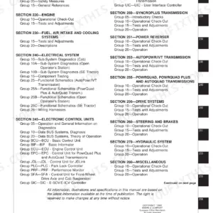
| General Information | 9-66 | Safety Information, General Specifications, Torque Values, Fuels and Lubricants, Inspection Procedure |
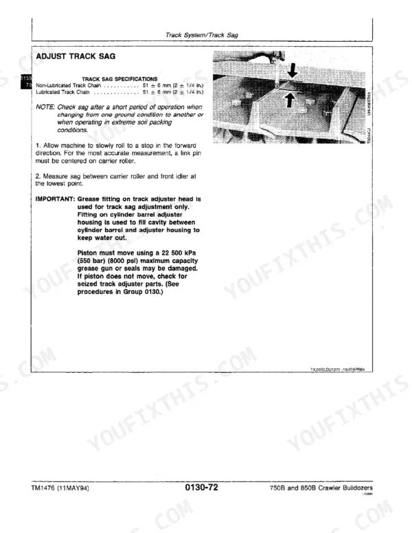
| Tracks | 67-130 | Track System, Carrier Roller Wear, Track Roller Wear, Track Shoe Grouser Wear, Track Sag Adjustment |
| Axles and Suspension Systems | 131-166 | Drive Axle Housing and Support, Axle Shaft, Bearings and Reduction Gears, Planet Housing, Final Drive |
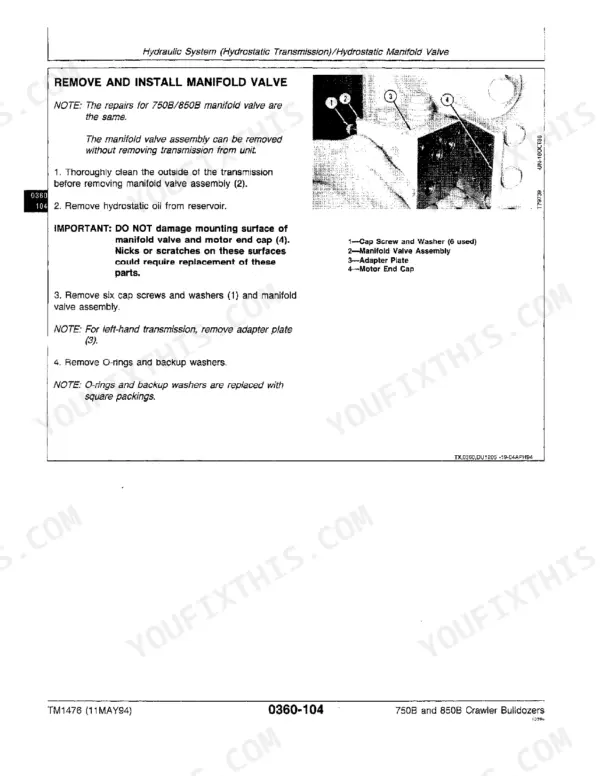
| Transmission | 167-266 | Hydrostatic Transmission, Control Linkage, Drive Shaft and U-Joints, Hydraulic System, Transmission Control Valve |
| Engine | 267-292 | Engine Removal and Installation, Oil Pan, Fuel System Bleed, Fan Belt Tightener |
| Engine Auxiliary Systems | 293-326 | Cold Weather Starting Aid, Cooling System, Speed Controls, Intake System, External Exhaust, Fuel Supply |
| Park Brake | 355-374 | Park Brake Removal and Installation, Control Linkage, Park Brake Pedal, Hydraulic System |
| Electrical System | 381-428 | Batteries, Alternator, Lighting System, Wiring Harness, Instruments and Indicators, Starting Motor |
| Operator's Station | 437-500 | Cab Removal, Operator Enclosure, Windowpane, Seat and Seat Belt, Heating and Air Conditioning |
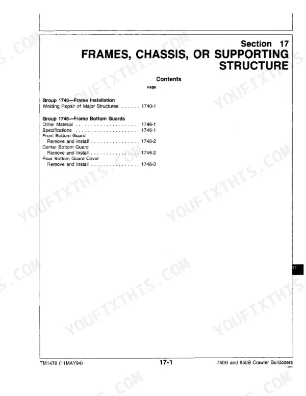
| Bulldozer | 521-564 | Angledozer Blade, Tilt Cylinder, Controls Linkage, Frames, Hydraulic System, Dozer Control Valve |
| Dealer Fabricated Tools | 565-574 | Compressor Holding Fixture, Track Nut Removal Tool, Final Drive Lifting Tool, Hydrostatic Pump Repair Stand |
Quick Reference Specifications
| Specification | Value | Page |
|---|---|---|
| Hydraulic System (Hydrostatic Transmission) | Group 0360 | p. 3 |
| Axle Shaft, Bearings and Reduction Gears | Group 0250 | p. 3 |
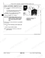
| Bypass valve cap screws torque | 50 N·m (37 lb-ft) | p. 328 |
| Cap screws (B) torque | 15 N·m (130 lb-in.) | p. 330 |
| High Pressure Relief Valve O-Ring | (2 used) | p. 375 |
| High Pressure Relief Valve Backup Ring | (2 used) | p. 375 |
| Adjusting Spring (D) Test length | 24 ± 2 N (5.4 ± 0.5 ib force) | p. 392 |
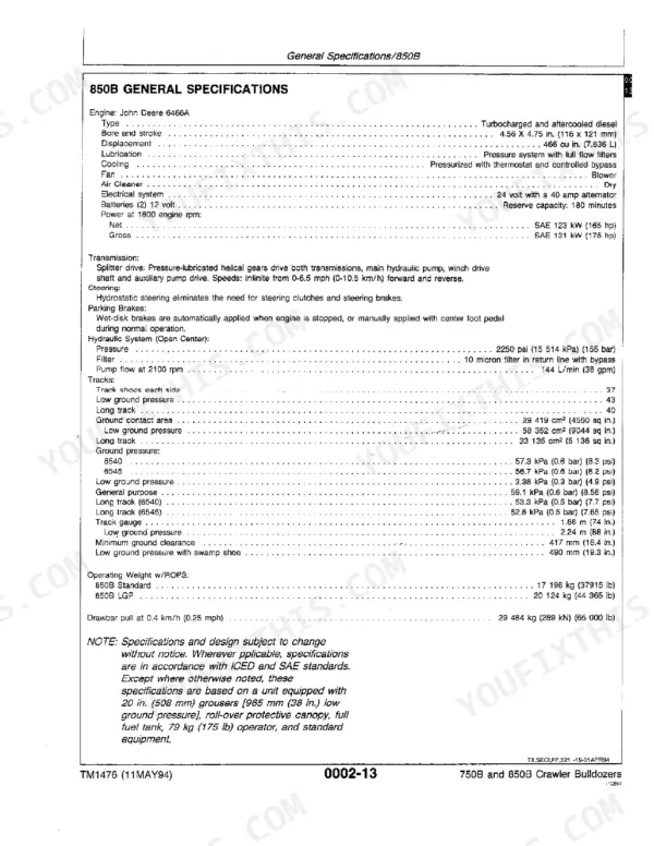
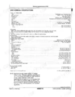
| 850B Engine Displacement | 7.635 L | p. 33 |
John Deere 750B, 850B, 750B Crawler Bulldozer, 850B Crawler Bulldozer Common Problems This Manual Covers
Reduced track power, machine hesitates or won't drive forward or reverse under load
Start in the Transmission section, pages 167-266, and check the displacement control valve servo piston for sticking before condemning the pump. Tighten the control valve cap screws (B) to 15 N·m (130 lb-in.) per the spec on page 330 if you've had the valve apart, since an undertorqued cover is a frequent cause of erratic displacement. Test control valve cartridge spring tension against the 24 ± 2 N test length on page 392 before swapping parts.
Manual Section: Transmission Control Valve p. 330Left track runs slower than right track, machine won't hold a straight line
Don't jump straight to the pump, this is usually a matched-pair displacement problem between the two hydrostatic circuits. Compare flow and pressure side to side using the Transmission section (pages 167-266) test procedures, then inspect the final drive on the slow side for internal wear per the Axles and Suspension Systems service procedures starting page 133. If one final drive shows more play than the other at the stub axle, that side is bleeding off power under load and needs to come apart.
Manual Section: Axles and Suspension Systems p. 133Tracks and ripper both stop moving in gear, machine sits dead with engine running
This points to blocked oil flow between pump and motor rather than an engine problem, since both circuits share the same hydrostatic supply. Work through the Hydraulic System procedures under Transmission (pages 167-266) and check the neutral shift linkage isn't hung up before opening any castings. Inspect the high pressure relief valve O-rings, listed as 2 used on page 375, for extrusion damage; a blown relief valve seal will dump pressure and stall both tracks at once.
Manual Section: Hydraulic System (Hydrostatic Transmission) p. 375Track won't free-wheel, resists pushing or towing even with drive disengaged
Free-wheeling problems on these machines almost always trace back to the final drive stub axle or center shaft binding internally. Follow the Axle Shaft, Bearings and Reduction Gears procedures in the Axles and Suspension Systems section (pages 131-166) and pull the center shaft rather than guessing at the pump. Check bypass valve cap screw torque against the 50 N·m (37 lb-ft) spec on page 328 if the bypass valve was recently serviced, since an overtight or leaking bypass valve will also prevent free-wheeling.
Manual Section: Axle Shaft, Bearings and Reduction Gears p. 328Frequently Asked Questions
How can a speed difference between the left and right sides of a John Deere 750B be addressed?
To address potential speed differences, adjust the steering linkage by checking for an over-center condition in the bell crank arm and ball joint on both sides. This adjustment ensures proper control and can help resolve discrepancies in speed between the left and right sides of the machine. p. 315
What is the procedure to reset the John Deere 750B hydraulic system after a filter change?
After changing the hydraulic filter on a John Deere 750B, move the FNR lever to neutral. Then, start and run the engine at a slow idle for 5 minutes to allow the filter elements to fill and purge air from the charge circuit. p. 360
What are the key inspection specifications for John Deere 750B hydrostatic pump components during overhaul?
During a hydrostatic pump overhaul for the John Deere 750B, inspect components against specific measurements. The Piston-to-Slipper End Play should be 0.20 mm (0.008 in.), and the Slipper Flange Thickness is 4.62 mm (0.182 in.). These values help determine if parts need replacement. p. 360
How do you fix john Deere 750B hydrostatic transmission overheating during summer operation, power drops under load?
Check fluid level and inspect the oil cooler fins for mud packing that blocks airflow, a common cause on 750B/850B units run in summer heat. Pull the hydrostatic pump repair stand reference in the Dealer Fabricated Tools section starting page 565 if you need to bench-test the pump. Verify case drain temperature stays below spec before returning the machine to work; repeated overheating points to internal pump leakage that will keep recurring until the pump is rebuilt. p. 167
Is this John Deere 750B manual a PDF I download?
Instant PDF download. You get the full 815-page searchable Technical Manual immediately after payment. Open it on your laptop, tablet, or phone right in the shop.
Does this John Deere 750B manual allow printing?
Absolutely. No DRM or copy protection. Print the whole manual or just the pages you need. Any home or office printer works.
Can I trace circuits with this John Deere 750B manual?
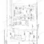
Yes, an electrical wiring diagram is included to help trace the main circuits.