
Part of the John Deere Repair Manuals.
Looking for the John Deere 750C, 850C repair manual PDF that dealer techs actually use? All 776 pages of TM1589 cover these crawler dozers from track frame to blade, including the 750C and 850C Series II machines. You get full wiring diagrams for the electrical system, hydraulic schematics for the hydrostatic transmission and dozer circuits, and step-by-step teardown procedures for tracks, final drives, axles, engine, park brake, and the operator's station. Exploded views walk you through every rebuild in the right order. Torque the engine mounts-to-main frame cap screws to 800 N-m (590 lb-ft), and switch the 850C to J20D low-viscosity HY-GARD when temperatures drop below -18°C. No more chasing a hydrostatic fault with forum guesses. Bookmarked with a full text layer; search any spec, jump to any section, and get that dozer pushing dirt again.
What's Inside This John Deere 750C, 850C Repair Manual
| System | Pages | Key Topics |
|---|---|---|
| General Information | 9-72 | Safety, Torque Values, Fuels and Lubricants, General Specifications, Fuels, Lubricants |
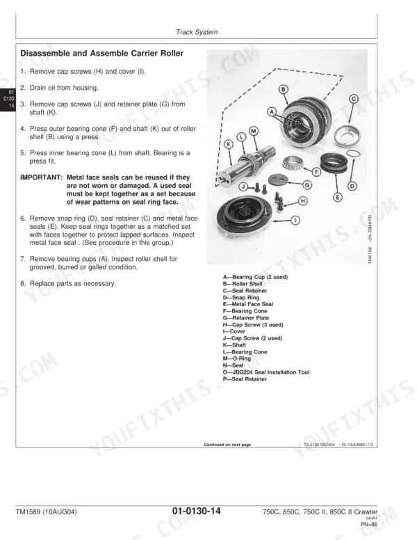
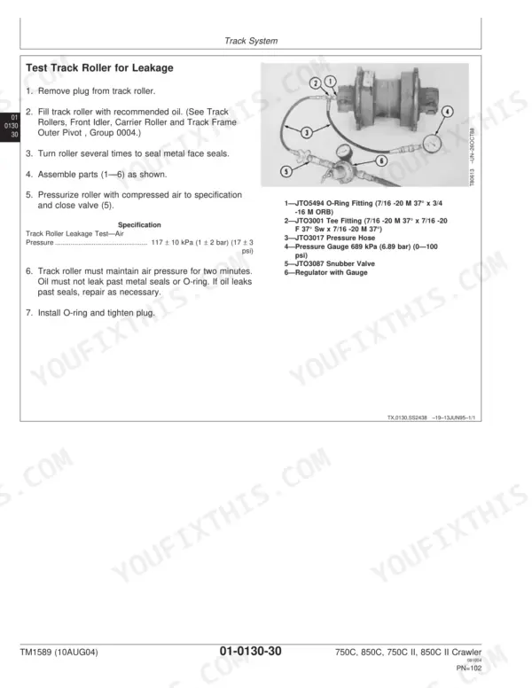
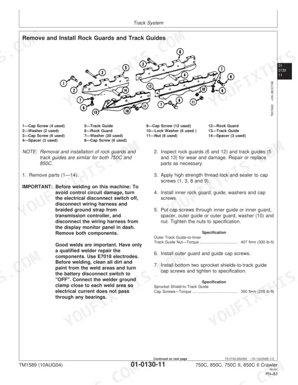
| Tracks | 73-198 | Track System, Rock Guards, Track Guides, Carrier Roller, Track Roller, Front Idler, Dealer Fabricated Tools |
| Axles and Suspension Systems | 199-238 | Drive Axle Housing, Axle Shaft, Bearings, Reduction Gears, Planet Housing |
| Transmission | 239-360 | Hydrostatic Pumps, Hydrostatic Motors, Control Linkage, Hydrostatic System, Oil Cooler Bypass Valve |
| Engine | 361-402 | Oil Pan, Fuel Filter, Fuel Injection Pump, Fuel Shut-Off Solenoid |
| Engine Auxiliary Systems | 403-466 | Cold Weather Starting Aid, Cooling System, Speed Controls, Intake System, Exhaust Systems, Fuel Supply Systems |
| Dampener Drive | 467-470 | Elements, Drive Elements |
| Park Brake | 471-488 | Control Linkage, Hydraulic System |
| Equipment Attaching | 489-494 | Drawbar, Extended Rigid Drawbar, Rigid Drawbar |
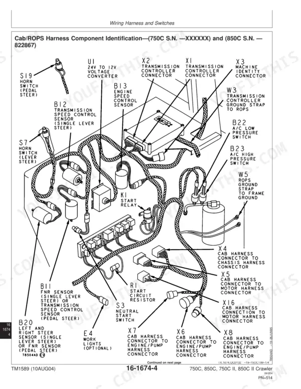
| Electrical System | 495-566 | Batteries, Alternator, Lighting System, Wiring Harness, System Controls, Motors and Actuators |
| Frames, Chassis, or Supporting Structure | 567-574 | Frame Installation, Frame Bottom Guards, Chassis Weights |
| Operator's Station | 575-648 | Operator Enclosure, Seat, Seat Belt, Heating System, Air Conditioning |
| Sheet Metal | 649-660 | Hood, Engine Enclosures, Grille, Grille Housing |
| Safety, Convenience and Miscellaneous | 661-664 | Horn, Warning Devices |
| Bulldozer | 665-776 | Removal and Installation, Blade, Controls Linkage, Frames, Hydraulic System |
Quick Reference Specifications
| Specification | Value | Page |
|---|---|---|
| John Deere HY-Gard Transmission and Hydraulic Oil | J20D (low viscosity) for temperatures below -18°C (0°F) | p. 65 |
| Transmission Speed Sensor Contact Point Voltage | 1.76—2.64 V | p. 261 |
| Transmission Speed Sensor Maximum Speed Voltage | 2.44—3.66 V | p. 261 |
| Engine Mounts-to-Main Frame Cap Screws Torque | 800 N•m (590 lb-ft) | p. 400 |
| Engine Front Mounts-to-Engine Cap Screws Torque | 278 N•m (205 lb-ft) | p. 400 |
| Fan Belt Strand Tension—750C (S.N.—831315) | 400 N (90 lb force) | p. 411 |
| Fan Belt—750C (S.N.—831315) Deflection | 19 mm at 111 N (3/4 in. at 25 lb force) | p. 411 |
| Approximate capacity of cooling system (750C) | 26.5 L (7 gal) | p. 416 |
| Approximate capacity of cooling system (850C) | 34 L (9 gal) | p. 416 |
| Battery Cable Cap Screws Torque | 9.2 N•m (82 lb-in.) | p. 497 |
| Battery Terminal Wire Lead Nut Torque | 3.73 ± 0.9 N•m (33 ± 8 lb-in.) | p. 507 |
| ROPS Mounting Bolts Torque | 410 ± 82 N•m | p. 47 |
John Deere 750C, 850C Common Problems This Manual Covers
John Deere 750C engine overheats pushing dirt under load, coolant surging out of the radiator overflow
Check fan belt tension first; a glazed or loose belt kills airflow before anything else shows up. Adjust strand tension to 400 N (90 lb force), or 19 mm deflection at 111 N, following the procedure on page 411. Verify the system holds its full 26.5 L (7 gal) charge, then blow packed debris out of the radiator core.
Manual Section: Engine Auxiliary Systems Repair p. 411Hydrostatic transmission loses drive response, fault codes F627 or F635 flashing on the monitor
Test the speed sensor circuits before throwing parts at it. Measure sensor output against the values on page 261: contact point voltage 1.76 to 2.64 V, slow speed 1.51 to 2.27 V, maximum speed 2.44 to 3.66 V. Readings outside range point to the sensor or its wiring; inspect connectors for corrosion and backed-out pins before condemning the control unit.
Manual Section: Transmission Repair p. 261Engine cranks slowly or will not turn over on cold mornings, dash lights dim
Clean both battery terminals down to bright metal and check the ground strap where it bolts to the frame. Torque the battery cable cap screws to 9.2 N•m (82 lb-in.) per page 497, and the terminal wire lead nuts to 3.73 ± 0.9 N•m (33 ± 8 lb-in.), page 507. Load test both batteries before blaming the starter.
Manual Section: Electrical System Repair p. 497Transmission faults keep coming back after speed sensor replacement, drive cuts in and out
Remove each sensor and reinstall it with the cap screws torqued to 15.3 ± 1.5 N•m (132 ± 12 lb-in.) on machines before S.N. 847804, or 11 N•m (97 lb-in.) on later units, per page 453. Wiggle-test the harness connectors while watching the monitor, and trace any intermittent circuit against the wiring diagram.
Manual Section: Engine Auxiliary Systems Repair p. 453Frequently Asked Questions
How do I perform a park lock or neutral start switch check on a 750C/850C?
To adjust the neutral start switch, you must use a multimeter to check for continuity. With the FNR lever in neutral, turn the switch in until the overload disappears and a minimum resistance value appears on the multimeter. Measure the distance between the washer and the switch to determine the required shim count, then tighten the switch to 34 N•m (25 lb-ft). p. 269
What are the replacement specifications for speed sensors?
The speed sensor mounting cap screws for the 850C (S.N. —847803) should be tightened to 15.3 ± 1.5 N•m (132 ± 12 lb-in.). For 850C machines with serial number 847804 and later, the sensor cap screw should be tightened to 11 N•m (97 lb-in.). p. 453
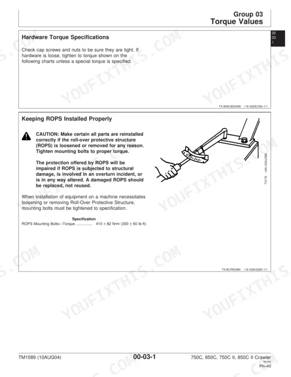
What is the torque specification for the ROPS mounting bolts?
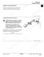
The ROPS mounting bolts must be tightened to a torque of 410 ± 82 N•m (300 ± 60 lb-ft). p. 47
What is the capacity of the 750C hydraulic reservoir?
The 750C hydraulic reservoir has a capacity of 67 L (18 gal). p. 695
What is the torque specification for the track shoe cap screws on a 750C?
For a 750C, the initial torque for 5/8 in. track shoe cap screws is 163 N•m ± 16 N•m (120 lb-ft ± 12 lb-ft), followed by an additional 1/3 turn (120°). p. 48
How is this John Deere 750C Repair Manual delivered?
All 776 pages arrive as one searchable PDF at checkout. Read it at the desk, then take the phone out to the machine.
Are there any print restrictions on this John Deere 750C manual?
No restrictions at all. Print individual pages, full chapters, or the entire manual. The PDF is completely unlocked.







Reviews
There are no reviews yet.