Part of the John Deere Repair Manuals.
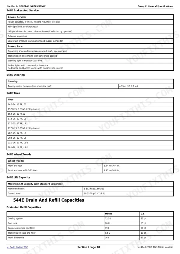
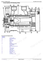
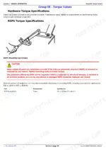
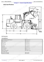
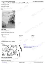
All 507 pages of this John Deere 544E Repair Manual PDF (OEM #TM1414) cover one machine family across five variants: 544E, 544E LL, 544E TC, 624E, and 644E 4WD Loaders. Inside you get wiring diagrams tracing every circuit, hydraulic schematics with complete fluid routing, and torque tables spanning axles, power shift clutch packs, steering, service brakes, and the loader system. Step-by-step procedures cover engine removal, secondary steering, cooling, operator station HVAC, and dealer fabricated special tools. Before buttoning up the hydraulic pump, confirm rear cover cap screws at 271 N·m (200 lb-ft) and verify the system relief valve spring free length against the factory 52.25 mm (2.057 in.) spec. Your loader isn't making money sitting in the yard. Bookmarked by section and keyword-searchable: pull it up on your tablet, walk to the machine, and start wrenching.
What's Inside This John Deere 544–644 Repair Manual
| System | Pages | Key Topics |
|---|---|---|
| Section I - General Information | 8-56 | Safety Information, Handle Fluids Safely-Avoid Fires, Prevent Battery Explosions, Prepare for Emergencies, Prevent Acid Burns, Handle Chemical Products Safely, Avoid High-Pressure Fluids |
| Wheels | 57-65 | Powered Wheels and Fastenings |
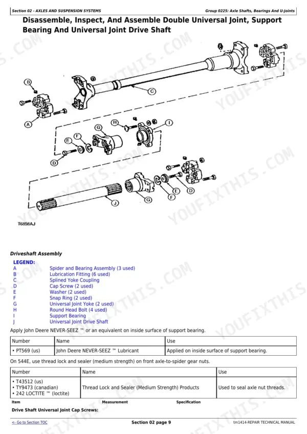
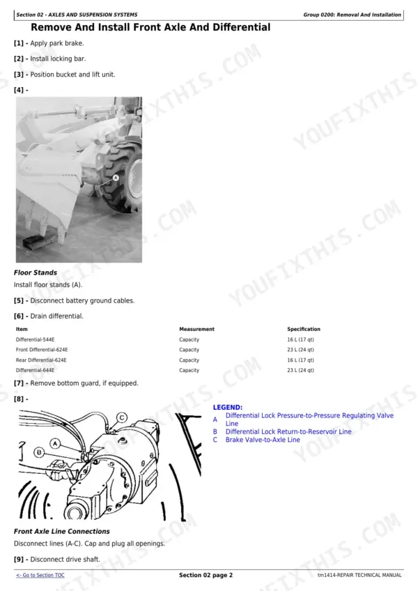
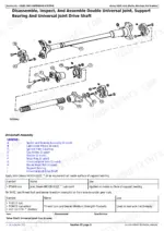
| Axles and Suspension Systems | 66-78 | Axle Shafts, Bearings and U-Joints, Axle Hydraulic System |
| Transmission | 79-174 | Transmission Controls Linkage, Input Drive Shafts and U-Joints, Gear, Shafts, Bearings and Power Shift Clutch |
| Engine | 175-212 | Engine Removal and Installation |
| Engine Auxiliary Systems | 213-235 | Cold Weather Starting Aids, Cooling System, Speed Controls, Intake System, External Fuel Supply System |
| Dampener Drive | 236-237 | Elements |
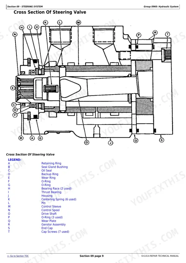
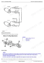
| Steering System | 238-274 | Secondary Steering, Steering Hydraulic System |
| Service Brakes | 275-294 | Service Brakes Active Elements, Service Brakes Hydraulic System |
| Park Brake | 295-300 | Park Brake Active Elements, Park Brake Controls Linkage |
| Equipment Attaching | 301-303 | Drawbar |
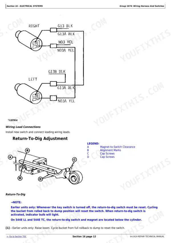
| Electrical Systems | 304-327 | Batteries, Support and Cables, Alternator, Regulator and Charging System Wiring, Lighting System, Wiring Harness and Switches |
| Frame or Supporting Structure | 328-342 | Frame Installation, Frame Bottom Guards, Chassis Weights |
| Operator′S Station | 343-406 | Operator Enclosure, Seat and Seat Belt, Heating and Air Conditioning |
| Loader | 407-496 | Bucket, Frames, Loader Hydraulic System |
| Dealer Fabricated Tools | 497-507 | Yoke Holding Tool, Input Pinion Shaft Adjusting Tool, Axle Adjusting Tool, Oil Supply Flange Back-Off Brackets, Stand Mounting Bracket, Cab Tilt Pivots and Hinges, Shaft Alignment Tool, Air Deflector Bushing |
Documents This Manual Refers To
The manufacturer cites these publications by number. We carry them:
Quick Reference Specifications
| Specification | Value | Page |
|---|---|---|
| Hydraulic pressure release procedure | Operate loader control valve, brake valve and steering valve | p. 68 |
| Torque converter type | Single phase, single stage | p. 24 |
| Main Hydraulic Pump Approximate Weight | 30 kg (66 lb) | p. 423 |
| Main Hydraulic Pump Rear Cover Cap Screws Torque | 271 N·m (200 lb-ft) | p. 423 |
| System Relief Valve Spring Free Length (approximate) | 52.25 mm (2.057 in.) | p. 423 |
| System Relief Valve Spring Test length at 2135 ± 213.5 N (480 ± 48 lb force) | 47.96 mm (1.888 in.) | p. 423 |
| Output Shaft-Rear Side of Transmission End Play | 0.3-0.5 mm (0.012-0.020 in.) | p. 138 |
| Steering Wheel-to-Shaft Nut Torque | 68 N·m (50 lb-ft) | p. 240 |
| Injection Pump Lever-544E, 624E Override | 2-4 mm (0.08-0.16 in.) | p. 223 |
| Brake Facing Oil Groove Depth (minimum) | 0.38 mm (0.015 in.) | p. 275 |
| Brake Disk Disk-to-Pinion Backlash | 1.02 mm (0.040 in.) | p. 275 |
| Pilot Control Valve (Two-Lever) Spool Return Passage Is Exposed With Spool In Neutral Distance | 1.02 ± 0.10 mm (0.040 ± 0.004 in.) | p. 463 |
John Deere 544–644 Common Problems This Manual Covers
John Deere 544E, 624E, 644E loader won't lift and steering goes dead after 2000+ hours
Check hydraulic fluid level first, then release residual pressure by cycling the loader control valve, brake valve, and steering valve as described on page 68. Inspect the gear-type pump for wear — the rear cover cap screws torque to 271 N·m (200 lb-ft) per page 423. If flow is weak or pressure stays low, pull the pump (approximately 30 kg) and check the system relief valve spring free length against the spec of 52.25 mm; test length under 2135 ± 213.5 N load must reach 47.96 mm. Torque the relief valve lock nut to 88 N·m on reinstall.
Manual Section: Loader p. 423Transmission won't engage or slips under load, output shaft feels loose
Remove the transmission per and measure output shaft end play at the rear. Spec is 0.3-0.5 mm (0.012-0.020 in.) per page 138 — anything outside that range means the bearing needs replacement. While you're in there, check oil pump-to-supply flange end play: same 0.30-0.50 mm window on page 152. For clutch pack overlap, minimum is 2.3 mm on 544E or 2.5 mm on 624E/644E (page 110) — below those numbers and the clutch won't hold.
Manual Section: Transmission p. 138Loader bucket functions work but response is sluggish or one function stops mid-cycle
Inspect the pilot control system. On single-lever machines, measure push plate-to-plunger clearance — spec is 0.000-0.254 mm (0.000-0.010 in.) per page 424; a worn plunger will bleed pressure. On two-lever machines, verify spool return passage exposure in neutral: 1.02 ± 0.10 mm per page 463. If the hydraulic oil looks milky or smells burnt after contamination, run the clean-up procedure on using the portable filter caddy before reinstalling any components.
Manual Section: Loader p. 463Brakes feel spongy, pedal travel is long, or machine won't hold on a grade
Bleed the hydraulic brake system per pages 292-293, then check accumulator precharge pressure — it must sit at 3447 ± 172 kPa (page 291). If braking is still soft after bleeding, pull a wet disk brake assembly and measure disk flatness: maximum allowable distortion is 1.14 mm (0.045 in.). Check oil groove depth on brake facings — minimum is 0.38 mm (0.015 in.) per page 275. Disk-to-pinion backlash limit is 1.02 N·m; beyond that, replace the disks.
Manual Section: Service Brakes p. 291Engine cranks but won't start or runs rough after sitting, fuel bleeding needed
Bleed air from the fuel system following pages 206-208 — this covers 544E, 624E, and 644E models. On 544E and 624E, also verify injection pump lever override clearance: spec is 2-4 mm (0.08-0.16 in.) per page 223. A lever sitting out of that range will prevent clean fueling regardless of how many times you cycle the starter. Check battery condition first using the test procedures on pages 304-305 — a weak battery on a cold morning can mask what is actually a fuel delivery problem.
Manual Section: Engine p. 206Steering feels heavy on one side or wanders, worse after hard work cycles
Start at the steering cylinder — disassemble and inspect seals per pages 253-261, paying attention to seal installation orientation. Verify steering wheel-to-shaft nut torque is 68 N·m (50 lb-ft) per page 240 before assuming internal damage. Check the secondary steering system (pages 238-274) for pressure loss; release residual hydraulic pressure first by cycling all valves as shown on page 68. If the cylinder checks out clean, the issue is likely in the steering hydraulic schematic circuit shown on page 246.
Manual Section: Steering System p. 253Frequently Asked Questions
How to reset hydraulic pressure on John Deere 544E loader?
To reset hydraulic pressure on the John Deere 544E loader, operate the steering and hydraulic functions to release pressure. This involves moving all control levers to relieve any trapped hydraulic pressure in the system. p. 344
What are the torque specs for the transmission bolts on John Deere 624E?
For the John Deere 624E, the torque specification for the Front Transmission Mounting Bracket-to-Transmission Cap Screws is 435 N·m (320 lb-ft). The Rear Transmission Mounting Bracket-to-Transmission Cap Screws should be torqued to 290 N·m (214 lb-ft). p. 79
What are the torque specs for the wheel hub nuts on John Deere 544E LL?
The torque specification for the Wheel Cap Screw on the John Deere 544E LL is 405 N·m (300 lb-ft). This applies to the fastenings for the powered wheels. p. 57
What are the replacement specifications for Gear-type hydraulic pump?
The Main Hydraulic Pump has an approximate weight of 30 kg (66 lb). The pump is serviceable only as an assembly, meaning it should be replaced as a complete unit if damaged or worn. p. 150
How will I receive this John Deere 544E & variants Repair Manual?
Immediate download of the complete 507-page searchable Repair Manual. Access it on any device, from a laptop at your desk to a phone in the field.
Can I print pages of this John Deere 544E & variants manual for my own shop?
Yes. Print the pages or sections you need for your own shop use. Any standard printer works.
Can I find wiring schematics in this John Deere 544E & variants manual?
Yes, this John Deere 544E & variants Repair Manual includes complete electrical wiring diagrams, wire routing, and connector pinouts.