
![John Deere 744K Repair Manual [Wheel Loader] TM10683](https://youfixthis.com/wp-content/uploads/2012/02/Manual_Download-300x300.jpg)
Part of the John Deere Repair Manuals.
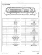
Need the factory specs for your John Deere Gator XUV 825i S4? This 752-page Technical Manual (OEM TM121519) PDF breaks down engine, electrical, power train, steering, and brake repair for this Utility Vehicle from the ground up. You get the complete main wiring harness with color codes, splice tables, and terminal tables across every serial number break, plus ECU and VCU pin locations and a full troubleshooting section that walks each DTC, from P0031 through P0116, step by step. Set the spark plug gap to 0.9-1.05 mm, top off the cooling system at 5.0 L, and follow the oil filter interval for the 812 cm3 engine exactly as John Deere specifies. No more guessing why the diagnostic light won't clear. It's bookmarked by section, so you can jump straight from cover to error codes without hunting through 752 pages.
What's Inside This John Deere XUV Gator 825i S4 Manual
| System | Pages | Key Topics |
|---|---|---|
| General Information | 5-26 | Safety Information, Fluid Handling, Battery Explosions, Protective Clothing, Machine Safety, Waste Disposal |
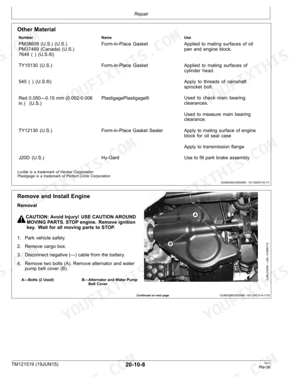
| Engine Repair | 27-110 | Engine Removal and Installation, Cylinder Head Reconditioning, Crankshaft and Piston Assembly, Oil Pump and Seals, Alternator and Starting Motor, Sensor Replacement |
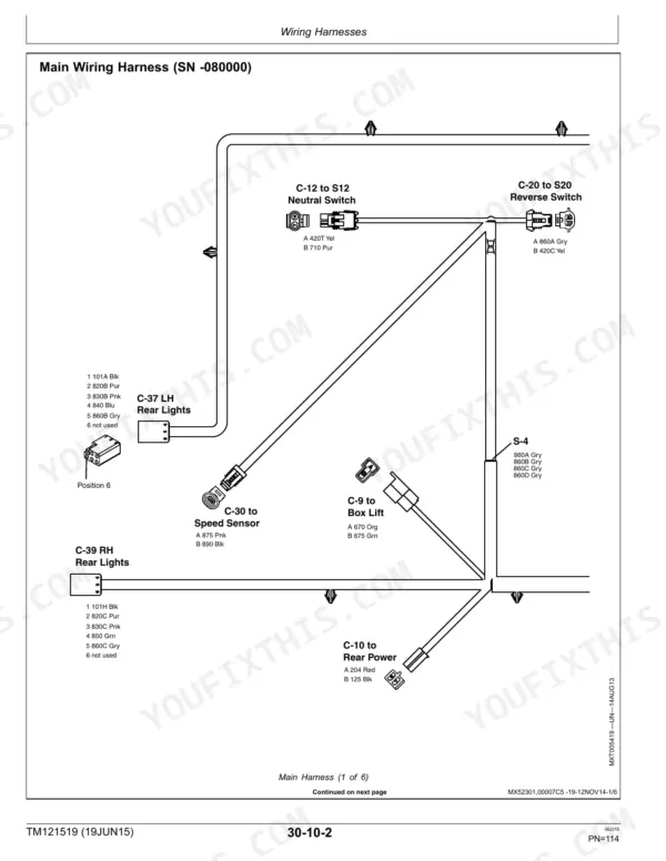
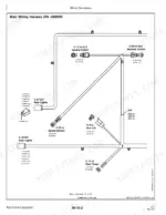
| Electrical Repair | 111-154 | Main Wiring Harness, Wiring Harness Color Codes, Wiring Harness Splice Table, Wiring Harness Terminal Table, Engine Wiring Harness, MFWD Service Kit Wiring Harnesses |
| Power Train Repair | 155-278 | Transmission Oil Change, Drive Clutch Repair, Driven Clutch Repair, Transmission Removal and Installation, Axles and Drive Shaft Repair, Mechanical Four Wheel Drive |
| Steering and Brake Repair | 279-354 | Steering Knuckle, Front Wheel Bearing, Ball Joint, Steering Column and Rack, Brake Rotor, Brake Pedal, Park Brake Cable, Lever and Service |
| Miscellaneous Repair | 355-378 | Wheels, Hood Latch and Hood, Front Fascia, Cargo Box and Bumper, Frame Components, Decals |
| Operator's Station Repair | 379-392 | Dash Panel, Front and Rear Seats, Seat Base and Under-Seat Storage Box, Operator's Station Trim, Roll-Over Protective Structure |
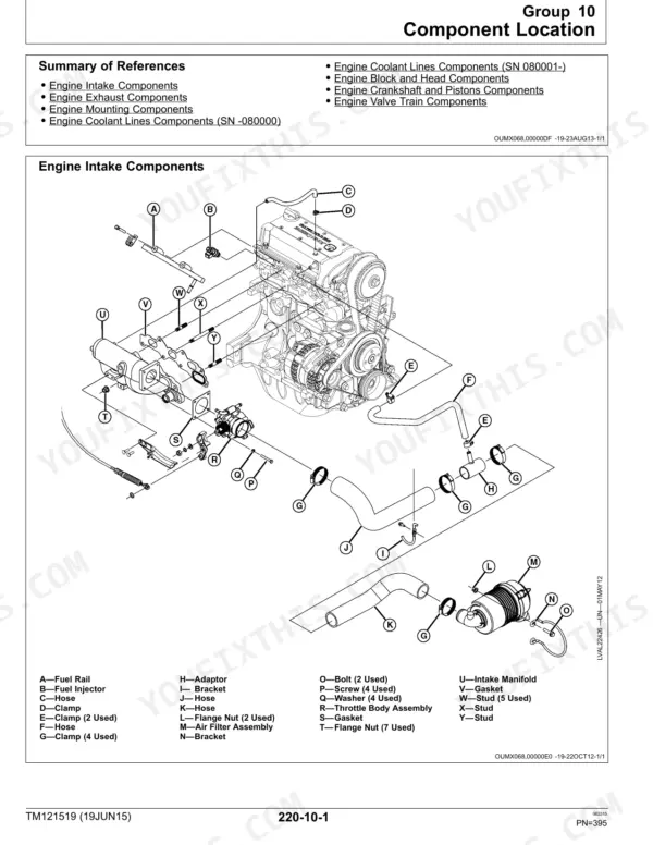
| Engine Operation, Tests, and Adjustments | 393-431 | Component Location (Intake, Exhaust, Mounting, Coolant Lines by Serial Number, Block and Head), Theory of Operation, Diagnosis, Tests and Adjustments |
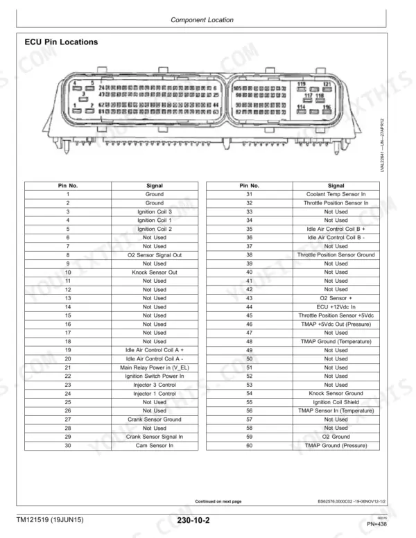
| Electrical Operation, Tests, and Adjustments | 432-638 | General Information, Component Location, Theory of Operation, Diagnosis - DTCs, Wiring Schematics, Electronic Controllers |
| Power Train Operation, Tests, and Adjustments | 639-674 | Component Location (Drive Clutch, Driven Clutch, CVT Belt, Transaxle), Theory of Operation, Diagnosis, Clutch and Transaxle Tests and Adjustments |
| Steering and Brake Operation, Tests, and Adjustments | 675-724 | Component Location (Steering Rack, Master Cylinder, Calipers, Park Brake), Theory of Operation, Diagnosis, Brake and Steering Tests and Adjustments |
| Miscellaneous Operation, Tests, and Adjustments | 725-736 | Component Location (Cargo Box Lift, Cab Accessories), Tests and Adjustments |
| Service Tools | 737-752 | Service Tools and Kits |
Quick Reference Specifications
| Specification | Value | Page |
|---|---|---|
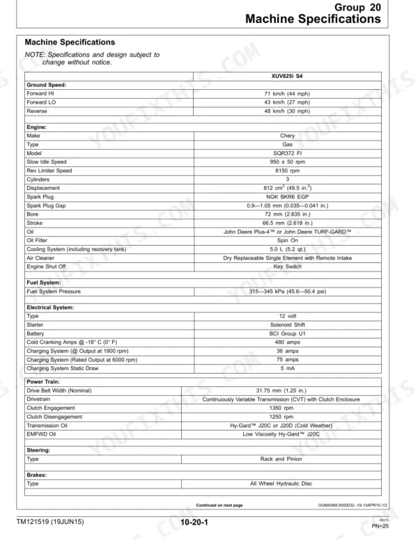
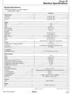
| Engine Displacement | 812 cm3 (49.5 in.3) | p. 25 |
| Spark Plug Gap | 0.9–1.05 mm (0.035–0.041 in.) | p. 25 |
| Cooling System Capacity (including recovery tank) | 5.0 L (5.2 qt.) | p. 25 |
| Fuel System Pressure | 315–345 kPa (45.6–50.4 psi) | p. 25 |
| Battery Cold Cranking Amps @ -18° C (0° F) | 480 amps | p. 25 |
| Drive Belt Width (Nominal) | 31.75 mm (1.25 in.) | p. 25 |
| Fuel Tank Capacity | 20.1 L (5.3 gal) | p. 26 |
| Crankcase Capacity (with Filter) | 2.2L (2.3 qt.) | p. 26 |
| Transmission Oil Capacity | 4.3 L (4.5 qt.) | p. 26 |
| EMFWD Front Differential Capacity | 660 mL (22 oz.) | p. 26 |
John Deere XUV Gator 825i S4 Common Problems This Manual Covers
John Deere XUV 825i S4 steering shaft separates from the steering rack assembly during operation
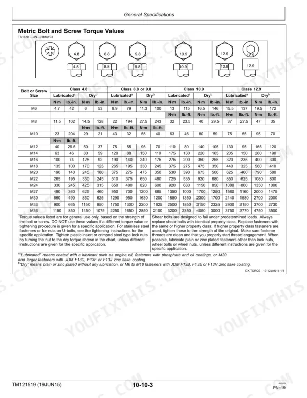
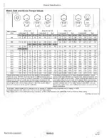
Inspect the steering shaft coupling and rack mounting bolts at the joint immediately; check for elongated bolt holes or a sheared pinch bolt. Torque the steering shaft pinch bolt to spec per the general torque specifications on page 19, replace any bolt showing thread deformation, and verify the steering rack is centered per the criteria on page 675 before returning the machine to service.
Manual Section: Steering and Brake Operation, Tests, and Adjustments p. 675Engine warms up, stalls, and won't restart until it cools back down
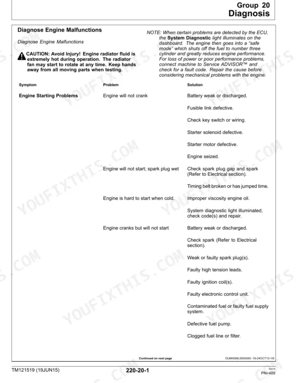
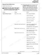
Check the engine malfunction diagnosis chart on page 409 for hot restart faults. Test fuel pump pressure against the 315-345 kPa (45.6-50.4 psi) spec while the engine is still warm; a reading below spec points to a heat-soaked fuel pump or vapor lock. Verify the pressure test procedure detailed in the diagnostic test values on page 417 before condemning the pump.
Manual Section: Engine Operation, Tests, and Adjustments p. 4094WD solenoid won't engage or refuses to disengage, drive mode stuck in one setting
Start diagnosis at the electrical operation and tests section on page 432. Confirm battery output meets the 480 amp cold-cranking spec on page 25 before chasing the solenoid, since a weak battery mimics solenoid failure. Check the DTC reference for related 4WD circuit codes, then swap the solenoid and retest engagement in both low and high range.
Manual Section: Electrical Operation, Tests, and Adjustments p. 432Primary clutch spider cracks, CVT shifts hard and belt slips under load
Pull the drive belt and inspect the primary clutch spider arms for cracking or excessive wear per the power train diagnosis on page 639. Measure drive belt width against the 31.75 mm (1.25 in.) nominal spec on page 25; a belt worn narrower than spec confirms clutch sheave misalignment. Replace the spider assembly and belt together, then check sheave alignment before road testing.
Manual Section: Power Train Operation, Tests, and Adjustments p. 63920-amp key switch fuse blows repeatedly within minutes of replacing it
Pull the electrical pinout diagram and trace the circuit feeding the 20-amp key switch fuse for a chafed harness or pinched wire. Disconnect accessories one at a time while metering current draw; a circuit pulling more than 20 amps confirms a short. Repair the damaged wire, reinstall a fresh 20-amp fuse, and cycle the key switch to confirm it holds.
Manual Section: Electrical Operation, Tests, and AdjustmentsWheel bearings and ball joints show excessive play and noise over turns
Jack up each corner and check for play in the wheel bearings and ball joints per the steering and brake diagnosis section on page 675. Grab the tire at 12 and 6 o'clock and rock it; any detectable movement means the bearing or joint is worn. Replace worn components in pairs and re-torque per the general torque specifications on page 19 before test driving.
Manual Section: Steering and Brake Operation, Tests, and Adjustments p. 675Frequently Asked Questions
How to reset John Deere Gator 825i S4 service indicator?
The manual does not provide an explicit procedure for resetting a service indicator or service light. Information on display panel programming is available in Section 230, Group 40, but it focuses on programming machine model, version, and tire size, not service resets. p. 607
What are the torque specs for John Deere Gator 825i S4 wheel lug nuts?
The torque specifications for wheel lug nuts vary by wheel type. For Aluminum Alloy Wheels, the torque is 142 N·m (105 lb.-ft.), and for Steel Wheels, it is 108 N·m (80 lb.-ft.). p. 357
What do error codes on John Deere Gator 825i S4 mean?
The manual provides a comprehensive list of Error Codes (DTCs) and their descriptions. For example, P0031 indicates an O2 Sensor Heater Circuit Low (Bank1 Sensor 1), meaning the O2 sensor is not heating properly. p. 501
How to reset throttle body on John Deere Gator 825i S4?
The manual describes procedures for replacing the throttle body and adjusting the throttle cable, but it does not provide an explicit 'reset' procedure for the throttle body itself. For adjustment, refer to the 'Adjust Throttle Cable' procedure on page 418. p. 109
What are the torque specs for John Deere Gator 825i S4 engine bolts?
Various engine bolts have specific torque specifications. For instance, the Engine Mount to Engine Block M10 Cap Screw requires 73 N·m (54 lb.-ft.), while the Valve Cover Bolt requires 6 N·m (53 lb.-in.). Cylinder Head Bolts have a three-pass tightening sequence: Initial Pass at 30 N·m (22 lb.-ft.), Second Pass at 50 N·m (37 lb.-ft.), and Final Pass at 70 N·m (51 lb.-ft.). p. 30
Is this John Deere Gator XUV 825i S4 Technical Manual a digital download?
You get a 752-page searchable PDF that downloads instantly after checkout. Open it on your laptop, tablet, or phone, and bring it right to the shop floor.
Can I print pages of this John Deere Gator XUV 825i S4 manual for my own shop?
Yes. Print individual pages or full chapters for your own shop use, on letter or A4 paper.







