

Part of the Kubota Repair Manuals.
This is the Kubota Workshop Manual for the M7040DT-SU tractor, powered by the V3307-DI-E2 diesel engine. It runs 398 pages with a searchable text layer and follows the machine system by system from the front of the tractor to the back.
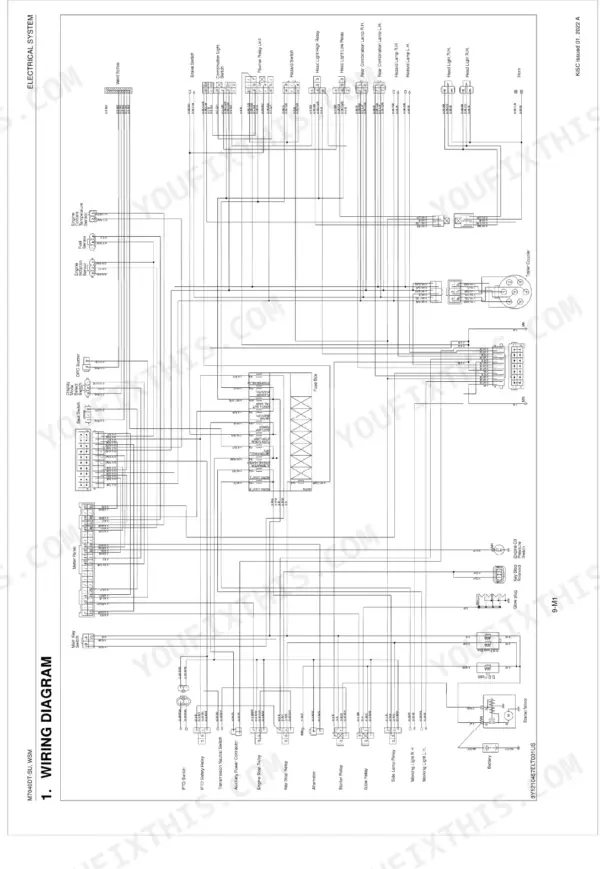
Coverage includes the engine, the traveling and PTO clutches, the transmission with its shuttle and hi-range shift sections and four wheel drive, the rear axle, brakes, front axle, steering, the hydraulic system and three point hitch, and the electrical system with wiring diagrams. Each area carries factory specifications, tightening torques, troubleshooting, and disassembly and assembly steps.
Use it to chase down a clutch, transmission, or hydraulic fault, set correct clearances and torques, or rebuild a system on your own M7040DT-SU rather than working from guesswork or partial online notes.
What's Inside This Manual
| System | Pages | Key Topics |
|---|---|---|
| Information | 4-14 | |
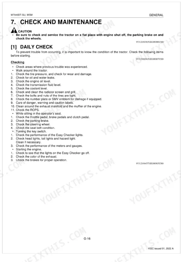
| General | 15-95 | Tractor Identification (Model Name and Serial Numbers, Cylinder Number) |
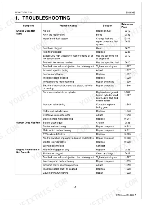
| Engine | 96-183 | Engine Body, Cylinder Block, Cooling Jacket, Half-Floating Head Cover, Cylinder Head, Center Direct Injection System (E-Cdis), Gear Train Configuration, Piston |
| Clutch | 184-214 | Travelling Clutch (Features, Linkage), PTO Clutch (Structure, Oil Flow, Valve), Troubleshooting (Travelling Clutch, PTO Clutch) |
| Transmission | 215-255 | Structure, Traveling System (Main Gear Shift Section, Shuttle Shift Section, Hi-Range Shift Section, Shift Linkage Mechanism, Four Wheel Drive Section), PTO System |
| Rear Axle | 256-268 | Features, Disassembling Planetary Gear, Disassembling Rear Axle, Thrust Collar Thickness |
| Brakes | 269-280 | Brake Pedal Free Travel, Brake Pedal and Linkage, Brake Case, Brake Cam Lever Movement, Cam Plate Flatness, Height of Cam Plate and Ball, Brake Disc Wear, Plate Wear |
| Front Axle | 281-302 | 4 Wheel Drive, 4WD Model, Adjusting Toe-In, Toe-In Adjustment, Axial Sway of Front Wheel, Adjusting Front Axle Pivot, Front Wheel Steering Angle (4WD Model), Separating Front Axle |
| Steering | 303-320 | Structure (Steering Mechanism), Troubleshooting, Servicing Specifications (Hydraulic Pump, Steering Controller, Steering Cylinder), Tightening Torques |
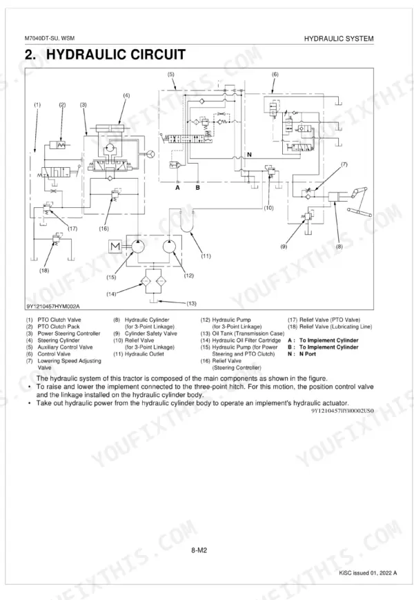
| Hydraulic System | 321-347 | Structure, Hydraulic Circuit, Hydraulic Circuit for Three Point Hydraulic System, Hydraulic Block, Linkage Mechanism, Troubleshooting, Servicing Specifications, Tightening Torques |
| Electrical System | 348-398 | Wiring Diagram, Electrical Circuit Detailed Chart (Starting System and Charging System, Lighting System, Meter Panel) |
Documents This Manual Refers To
The manufacturer cites these publications by number. We carry them:
Quick Reference Specifications
| Specification | Value | Page |
|---|---|---|
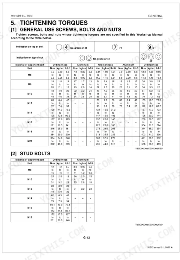
| Cylinder head mounting screw torque (Bolt head with stamp "10") | 186 to 196 N-m (19.0 to 20.0 kgf-m, 137 to 145 lbf·ft) | p. 28 |
| Connecting rod screw torque | 68.6 to 73.5 N-m (7.0 to 7.5 kgf-m, 50.6 to 54.2 lbf·ft) | p. 28 |
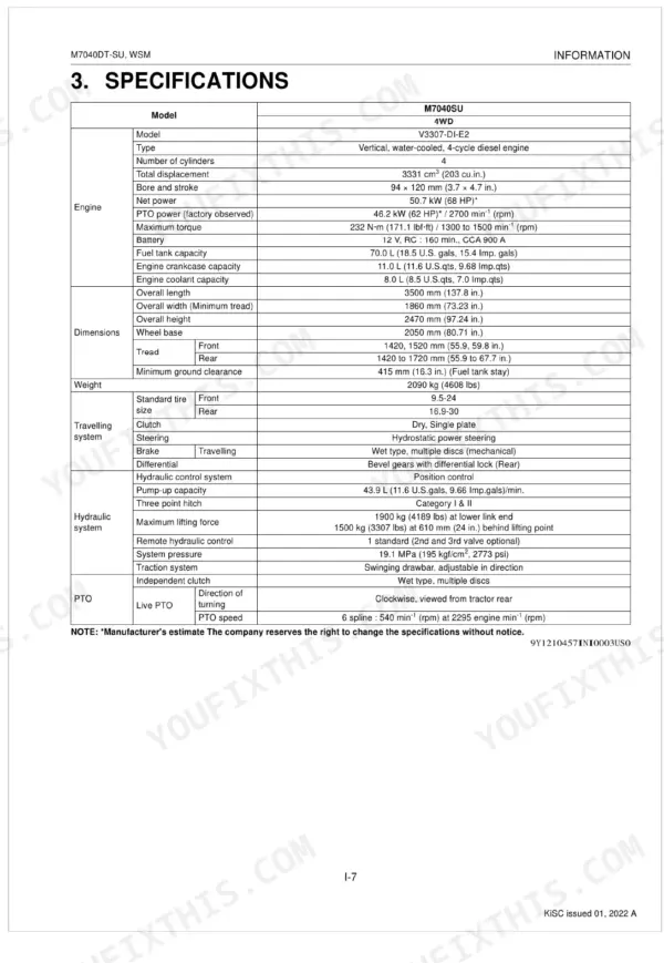
| Engine Oil Capacity | 11.0 L | p. 26 |
| Transmission Case Capacity | 44.0 L | p. 26 |
| Front Differential Gear Case Capacity | 6.6 L | p. 26 |
| Coolant Capacity | 8.0 L | p. 26 |
| Cylinder Head Mounting Screw Torque | 186 to 196 N-m | p. 122 |
| Engine Oil Pressure (At Idle Speed) | 49 kPa | p. 120 |
| Alternator Belt Tension (Deflection) | 16 to 17 mm | p. 120 |
| Injection Pressure (1st stage) | 18.63 to 19.61 MPa | p. 121 |
| Piston Ring Gap (Top ring) | 0.25 to 0.40 mm | p. 118 |
| Valve Stem O.D. (Intake and exhaust) | 6.960 to 6.975 mm | p. 116 |