
Part of the John Deere Repair Manuals.
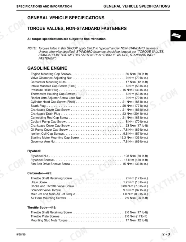
All 951 pages of this John Deere 425, 445, 455 Technical Manual PDF (OEM TM1517) focus on one job: putting your lawn and garden tractor back to factory spec. You get full wiring harness diagrams and electrical schematics for each model, hydrostatic power train and hydraulic schematics, and troubleshooting charts that walk you through power, cranking, ignition, and PTO circuit diagnosis. Exploded views back up the rebuild procedures on both the gasoline FD620D and the diesel, from cylinder head to charge pump. Gap the plugs at 0.25 mm, torque them to 20 N-m, and confirm bypass valve opening pressure at 96 kPa (14 psi) before you button it up. No more chasing electrical gremlins with a multimeter and a prayer. Bookmarked with a real text layer: jump to any circuit, search any spec, fix the tractor.
Complete the set for your 425, 445, 455
- Operator Manual: John Deere 425, 445 Operator Manual
Other edition of this manual
What's Inside This John Deere 425, 445, 455 Manual
| System | Pages | Key Topics |
|---|---|---|
| Introduction | 2 | Table of Contents, General Diagnostic Information, Specifications, Electrical Wiring Harness Legend, Component Location, System Schematic |
| Safety | 3-7 | |
| Specifications and Information | 8-31 | General Vehicle Specifications, Metric Fastener Torque Values, Gasoline Engine, Diesel Engine, Hydrostatic Transmission Oil, Gear Case Oil |
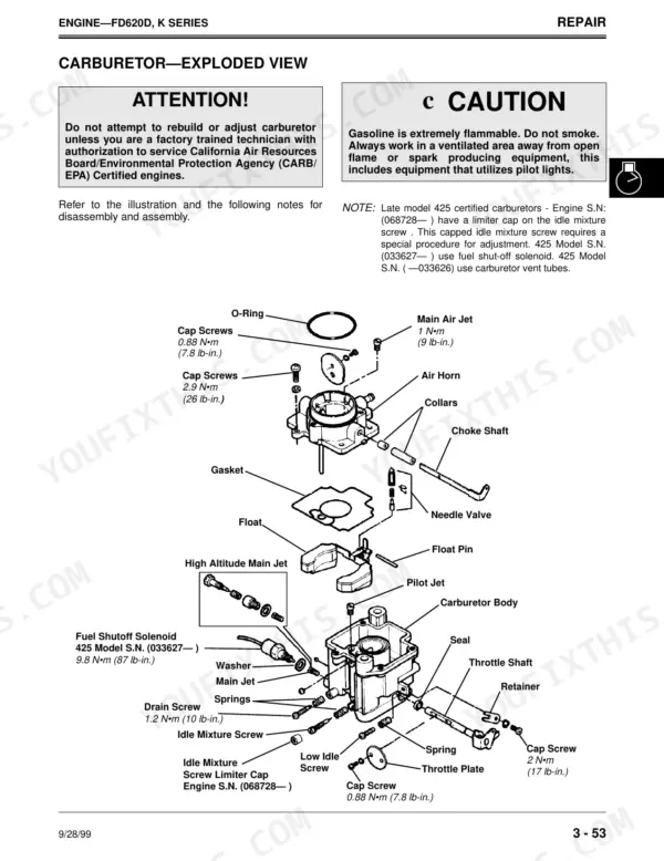
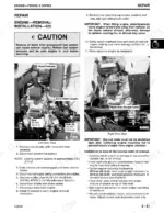
| Engine?Fd620D, K Series | 32-109 | Engine Removal, Carburetor, Governor, Cylinder Head, Crankshaft, Oil Pump |
| Diesel Engine | 110-217 | Cooling System, Fuel Injection, Oil Pan, Timing Gear, Alternators, Cylinder Head |
| Electrical Specifications and General Information | 218-231 | Specifications, Theory, Diagnostic Information, Wire Color Abbreviation Chart |
| Component Location and Wiring Harnesses - 425 | 232-266 | Component Location (S.N., 070000 and 070001, ), Electrical Component Legends, Main Wiring Harness W1 Early and Late Models, Rear PTO Wiring Harness W2, Main Electrical Schematics |
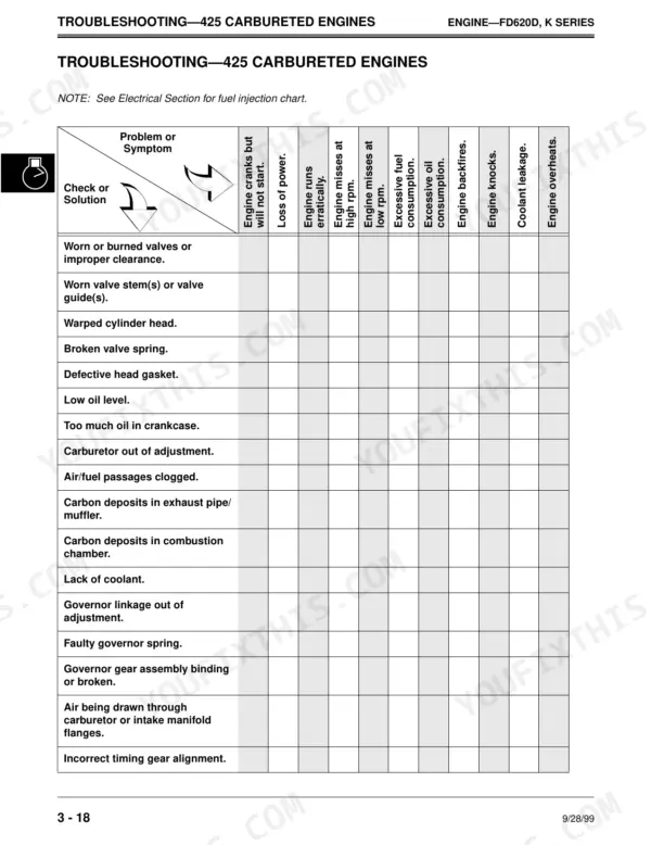
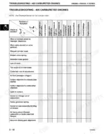
| Troubleshooting and Circuit Diagnosis - 425 | 267-321 | Electrical System Quick Test per Serial Range, Electrical System Troubleshooting Chart, Control/Fuse Module, Power Circuit Operation and Schematics, Power Circuit Diagnosis and Test Points |
| Indicator Lights, Gauges, and PTO Circuit Diagnosis - 425 | 322-374 | Indicator Lights, Hourmeter, Coolant Temperature Gauge, Fuel Gauge, PTO Circuit Diagnosis |
| Component Location and Wiring Harnesses - 445 | 375-425 | Component Location (S.N., 070000 and 070001, ), Electrical Component Legends, Main Wiring Harness W1 (S.N., 031361, 031362, 070000, 070001, Rear PTO Harness W2, Main Electrical Schematics |
| Troubleshooting and Circuit Diagnosis - 445 | 426-524 | Electrical System Quick Test, Electrical System Troubleshooting Chart, Control/Fuse Module, Power Circuit Operation and Schematics, Fuel Pump Circuit Diagnosis, Power Circuit Test Points |
| Fuel Injection and Diagnostic Light Circuit Diagnosis - 445 | 525-562 | Fuel Injection Sensor, Diagnostic Light Circuit, Fuel Injector and Pump Circuit Diagnosis |
| Component Location, Wiring Harnesses, and Troubleshooting - 455 | 563-763 | Component Location, Wiring Harnesses, Electrical Schematics, Troubleshooting Charts, Diesel Module Test |
| Hydrostatic Power Train | 764-841 | Directional Control Valves, Charge Pump, Differential, PTO Clutch, Hydrostatic Transmission, Rear Axle Assembly |
| Steering | 842-879 | Steering Column, Steering Valve, Steering Cylinder, Front Axle, Rear Steering Linkage, Pivot Assembly |
| Brakes | 880-893 | Brake System Operation, Brake/Differential Linkage, Brake Assembly, Brake Switch, Transaxle Brake Cover |
| Hydraulics | 894-923 | Hydraulic System, Hydraulic Control Valve, Lift Cylinder, Hydraulic Schematic, Charge Pump |
| Miscellaneous | 924-937 | Air Cleaner, Muffler, Fan Belt, Radiator, Fuel Tank, Lift Linkage |
Quick Reference Specifications
| Specification | Value | Page |
|---|---|---|
| 425 | ||
| Spark Plug | 20 N•m (177 lb-in.) | p. 10 |
| All Models | ||
| Minimum Pressure (Carburetor—425) | 10 kPa (1.5 psi) | p. 34 |
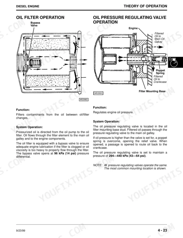
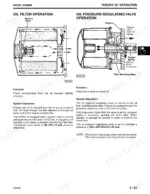
| Bypass valve opening pressure | 96 kPa (14 psi) | p. 134 |
| Oil pressure regulating valve setting | 294—440 kPa (43—64 psi) | p. 134 |
| Air intake system pressurization | 34—69 kPa (5—10 psi) | p. 146 |
| Normal air filter restriction | 380 mm (15 in.) vacuum | p. 146 |
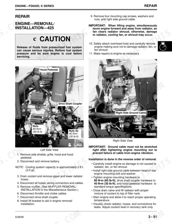
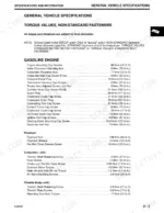
| Engine Mounting Cap Screws Torque | 80 N•m (60 lb-ft) | p. 10 |
| Spark Plug Torque (Gasoline Engine) | 20 N•m (177 lb-in.) | p. 10 |
| Flywheel Nut Torque (Gasoline Engine) | 108 N•m (80 lb-ft) | p. 10 |
| Diesel Engine Nozzle Torque | 50 N•m (37 lb-ft) | p. 11 |
| 445 | ||
| Spark plug gap/clearance | 0.25 mm (0.010 in.) | p. 71 |
| Fuel pump operating time | 2 seconds | p. 71 |
John Deere 425, 445, 455 Common Problems This Manual Covers
Engine runs rough on one cylinder, misses under load, noticeable power loss at full throttle
Remove both spark plugs and read them; a wet or fouled plug points at the dead cylinder. Gap new plugs on the 445 to 0.25 mm (0.010 in.), spec on page 71, and torque them to 20 N•m (177 lb-in.). If the miss stays, swap coils between cylinders and run a compression test on both sides.
Manual Section: Engine?Fd620D, K Series p. 71Fuel injected engine cranks and pump ticks but never fires, or dies right after starting
Verify the pump primes for a full 2 seconds at key-on, then test fuel pressure at the rail; the injected engine needs 172 to 186 kPa (25 to 27 psi). If pressure is low, replace the in-line filter and retest. Clean the PTO switch contacts too; dirty contacts block the start interlock. Circuit tests begin on page 525.
Manual Section: Fuel Injection and Diagnostic Light Circuit Diagnosis - 445 p. 525Diesel engine overheats and loses power during heavy mowing in hot weather
Clean the radiator fins and engine intake screens first; most overheating starts there. Check the air cleaner with a restriction gauge and replace the primary element once vacuum reaches 635 mm (25 in.), spec on page 146. Verify coolant and oil levels, then confirm fast idle sits at 3350 ± 100 rpm per the spec on page 114.
Manual Section: Diesel Engine p. 146Mower blades keep spinning more than five seconds after the PTO switch is shut off
Test stop time with the engine at operating speed: disengage the PTO and count; blades must stop within 5 seconds. If they coast longer, service the PTO brake and inspect the clutch pack for worn friction material. Clutch and brake teardown procedures are in the Hydrostatic Power Train section starting on page 764.
Manual Section: Hydrostatic Power Train p. 764Frequently Asked Questions
How do I reset the PTO switch on a John Deere 425/445/455?
The PTO switch is reset by returning it to the OFF position. If the PTO switch is in the ON position, the safety circuit prevents the PTO relay from energizing. p. 149
What do the blinking error lights mean on a John Deere 445?
The injection system failure light blinks diagnostic codes to indicate sensor issues. For example, 'Long, short, short' indicates an air temperature sensor circuit fault, while 'Long, short, short, short' indicates a coolant temperature sensor circuit fault. p. 146
What is the torque specification for the cylinder head bolts on a 425/445/455 engine?
For the FD620D engine, the cylinder head cap screws should be torqued in sequence to an initial torque of 13 N•m (115 lb-in.) and a final torque of 21 N•m (186 lb-in.). p. 98
How do you fix john Deere 425 cranks but will not start, fuel pump silent with no tick at key-on?
Check the fuse block and fuel pump circuit before condemning the pump. Test pump output; the carbureted 425 needs a minimum 10 kPa (1.5 psi), spec on page 34. If pressure checks good, work through the no-start charts starting, then trace the pump wiring in the 425 circuit diagnosis section on page 267. p. 34
How is this John Deere 425 Technical Manual delivered?
You get a 951-page searchable PDF that downloads instantly after checkout. Open it on your laptop, tablet, or phone, and bring it right to the shop floor.
Can I print pages of this manual for my own shop?
Yes. Print the pages or sections you need for your own shop use. Any standard printer works.
Can I find hydraulic circuit diagrams in this John Deere 425 manual?
Yes. The manual includes a hydraulic system diagram covering the main circuits.








Reviews
There are no reviews yet.