
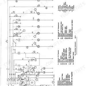
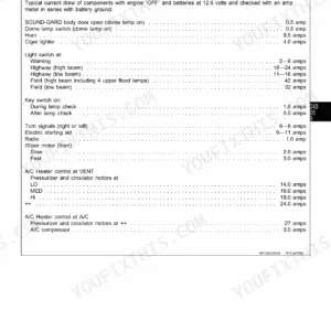
Part of the John Deere Repair Manuals.
CTM20 takes the John Deere 6101 diesel engine down to a bare block and walks it back up, 421 pages of Series 500 factory rebuild work that covers this engine on the stand. Disassembly and assembly sequences anchor the book, and roughly half of it is hands-on procedure: valve guide measurement, seat grinding, liner and piston removal, crankshaft and main bearing work, camshaft and timing gear train. Fuel system operation and tests run long, covering injection pump, nozzles, aneroid and supply pump checks. Torque the cylinder head cap screws to 200 N·m (150 lb-ft), then turn them an additional 90 to 100 degrees; oil pressure at rated speed should read 280 to 380 kPa (40 to 55 psi). A guessed clearance costs you a second teardown and a scrap crankshaft. Bookmarks and searchable text put you on the specification page you want before your coffee cools.
What's Inside This John Deere 6101 Manual
| System | Pages | Key Topics |
|---|---|---|
| Safety | 6-13 | Fluid Safety, Battery Safety, Emergency Preparedness, Acid Burn Prevention, High-Pressure Fluid Safety, Protective Clothing |
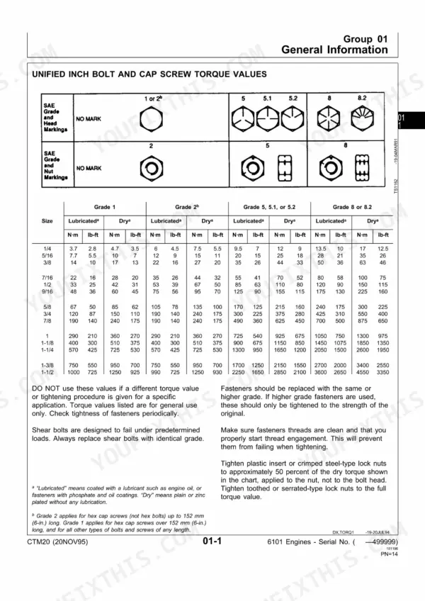
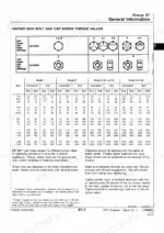
| General Information | 14-19 | Unified Inch Bolt and Cap Screw Torque Values, Metric Bolt and Cap Screw Torque Values, Engine Model Designation, Engine Nameplate Information, Engine Application Chart |
| Fuels, Lubricants, and Coolant | 20-33 | Diesel Fuel, Lubricity of Diesel Fuels, Engine Break-In Oil, Diesel Engine Oil, Oilscan and Coolscan, Alternative and Synthetic Lubricants, Grease, Engine Coolant Requirements |
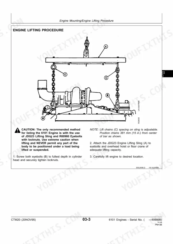
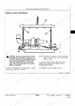
| Engine Mounting | 34-39 | Engine Repair Stand, Safety Precautions, Install 500 Series Adapters on Repair Stand, Engine Lifting Procedure, Clean Engine, Mount Engine on Repair Stand |
| Engine Rebuild Guide | 40-45 | Engine Disassembly Sequence, Sealant Application Guidelines, Engine Assembly Sequence |
| Cylinder Head and Valves | 46-85 | Special or Essential Tools, Service Equipment and Tools, Other Material, Specifications, Torques, Disconnect Turbocharger Oil Inlet Line, Check and Adjust Valve Clearance |
| Cylinder Block, Liners, Pistons and Rods | 86-127 | Special or Essential Tools, Specifications, Remove Pistons and Connecting Rods |
| Crankshaft, Main Bearings and Flywheel | 128-177 | Special or Essential Tools, Specifications, Crankshaft Front Oil Seal, Remove Crankshaft Main Bearings, Oil Pump Drive Gear |
| Camshaft and Timing Gear Train | 178-203 | Special or Essential Tools, Specifications, Check Camshaft End Play, Camshaft Drive Gear-to-Crankshaft Gear Backlash, Remove Camshaft, Camshaft Bushings |
| Lubrication System | 204-223 | Specifications, Oil Bypass Valve Housing and Oil Cooler Assembly, Oil Pressure Reg. Valve |
| Cooling System | 224-249 | Special or Essential Tools, Specifications, Remove Water Pump, Assemble Water Pump, Coolant Filter Conditioner, Check and Adjust V-Belt Tension |
| Air Intake and Exhaust System | 250-281 | Special or Essential Tools, Specifications, Diagnosing Turbocharger Malfunctions, Axial End Play Bearing Test |
| Fuel System | 282-331 | Special or Essential Tools, Specifications, Disassemble Fuel Supply Pump, Remove Fuel Injection Pump |
| Engine Tune-Up and Break-In | 332-341 | Altitude Performance, Preliminary Engine Testing, Tune-Up Recommendations, Dynamometer Testing, Engine Break-In Guidelines, Engine Break-In Instructions |
| Engine System Operation and Tests | 342-363 | Engine Test Specifications, Engine Sectional View, Lubrication System, Head Gasket Joint, Engine Compression Pressure, Cooling System |
| Air Intake System Operation and Tests | 364-373 | Manifold Pressure, Air Filter Restriction, Turbocharger, Aftercooler, Intake Manifold, Exhaust System |
| Fuel System Operation and Tests | 374-405 | Fuel Supply Pump, Fuel Injection Pump, Injection Nozzles, Aneroid, Hydraulic Aneroid Activator, Fuel Filter |
| Dealer Fabricated Tools | 406-407 | Cylinder Liner Holding Fixture |
Quick Reference Specifications
| Specification | Value | Page |
|---|---|---|
| Battery charging temperature | 16°C (60°F) | p. 6 |
| Cylinder Head Cap Screws | Initial 200 N·m (150 lb-ft), Final Tighten additional 90°—100° | p. 51 |
| Cylinder Head Cap Screw Torque | Initially 200 N·m (150 lb-ft), then 200 N·m (150 lb-ft), finally 90-100 degrees | p. 81 |
| Engine Oil Pressure @ Rated Speed | 280—380 kPa (40—55 psi) | p. 204 |
| Coolant conditioner filter base cap screw torque | 47 N·m (35 lb-ft) | p. 245 |
| Coolant heater flange nut torque | 68 N·m (50 lb-ft) | p. 249 |
| Fan Belt Tension (New Belts) | 422—463 N (95—104 lb) | p. 226 |
| Fan Belt Tension (Belts in Service) | 378—418 N (85—94 lb) | p. 226 |
| Thermostat Opening Temperature | 80—84°C (175—182°F) | p. 226 |
| Thermostat Initial Opening Range (71°C Rating) | 69—72°C (156—162°F) | p. 363 |
| Minimum No Load Oil Pressure at 800 rpm | 103 kPa (1.03 bar) (15 psi) | p. 360 |
| Cylinder Head Cap Screws Initial Torque | 200 N·m (150 lb-ft) | p. 51 |
John Deere 6101 Common Problems This Manual Covers
Hard starting, rough idle and black smoke after a fuel filter change or injector service
Bleed the system completely, then verify supply pump output. Minimum operating pressure is 200 kPa (2.0 bar) (29.0 psi) as specified on page 374. Pop test each nozzle on a tester: new nozzles open at 29000-29800 kPa (4200-4300 psi) per page 314, used ones must exceed 26200 kPa (3800 psi).
Manual Section: Fuel System Malfunctions p. 377Engine lacks power, slow acceleration and excessive black smoke under full throttle
Check air filter restriction first, then measure manifold pressure using the boost test procedure in the air intake section beginning on page 364. Spin the turbo shaft by hand and feel for drag or radial play. Set valve lash cold while you are in there: intake 0.33-0.43 mm (0.013-0.017 in.) per page 50.
Manual Section: Air Intake Malfunctions p. 365Belt squeal, charging fault and whining from the front of the engine after belt replacement
Set tension with a gauge, not by thumb feel. New belts run 422-463 N (95-104 lb) and belts already in service run 378-418 N (85-94 lb), both listed on page 226. Standard V-belts should deflect 19 mm (3/4 in.) under 89 N (20 lb-force). Check pulley alignment before you condemn the alternator.
Manual Section: Cooling System p. 247Frequently Asked Questions
What is the cylinder head cap screw torque spec for a John Deere 6101 diesel engine?
The initial torque for the cylinder head cap screws is 200 N·m (150 lb-ft). After the initial torque, they must be tightened an additional 90° to 100° using the TORQUE-TURN method. p. 51
How do you fix John Deere 6101 diesel engine oil pressure warning at idle, gauge drops below spec when hot?
Test pressure at the main gallery port before pulling the pan. Minimum no load pressure at 800 rpm is 103 kPa (1.03 bar) (15 psi) per page 360, and rated speed should hold 280-380 kPa (40-55 psi) as listed on page 204. Below that, measure rod and main bearing clearance. p. 204
How do you fix engine overheats under sustained load, coolant temperature climbs and warning light comes on?
Fill the system to 19 mm (3/4 in.) below the bottom of the radiator filler neck, the level given on page 339. Pull the thermostat and bench test it in heated water: a 71 degree C unit starts opening at 69-72 degrees C (156-162 degrees F) per the chart on page 363. Replace anything lazy. p. 227
How do you fix coolant in the oil or bubbles in the radiator, white smoke out the exhaust at startup?
Pressure test the cooling system cold, then check for combustion leakage at the head gasket joint using the tests starting on page 342. Torque the head cap screws to 200 N·m (150 lb-ft) in sequence, then turn each an additional 90 to 100 degrees. p. 81
Is this John Deere 6101 Technical Manual a digital download?
This is a 421-page searchable PDF ready for immediate download. Works on any device, so pull it up on your phone while you're under the hood. No shipping, no waiting.
Can I print pages of this John Deere 6101 manual for my own shop?
Yes. Print the pages you need for the job in your own shop, and bin them when they get greasy.









Reviews
There are no reviews yet.