
Part of the John Deere Repair Manuals.
This is the Operation and Test technical manual for John Deere 8120, 8220, 8320, 8420 and 8520 row-crop tractors built 1998-2004. It is the diagnostic book: service codes for the ACU, CCU, PCU and ECU controllers, observable symptom charts, system operational checks, electrical schematics and pressure test specs with the actual numbers - standby 30-40 bar, stall 196-210 bar, pilot 19-22 bar at the PS port. Coverage runs from engine, fuel/air and cooling through the powershift transmission, hydraulics, steering/brakes, operator station and the AMS side: GreenStar, AutoTrac, JDLink and Field Doc. This is the manual you open when the tractor throws a code or something quits, before you touch a wrench.
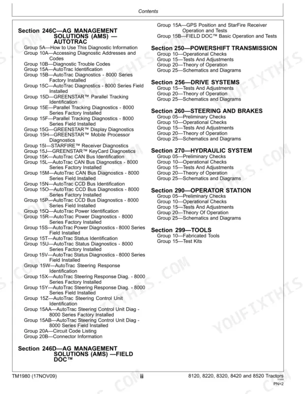
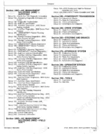
What's Inside This John Deere 8120-8520 Manual
| System | Pages | Key Topics |
|---|---|---|
| General | 5-79 | Safety, Standard Torque Charts, fuel/lubricant Specs, Diagnostic Tools |
| Service Codes | 80-841 | Acu, Ccu, Pcu and ECU Code Lists, Code Readout on Corner Post Display, Code Diagnostics |
| Observable Symptoms | 842-1072 | Symptom-To-Section Charts for Engine, Hitch, Hydraulics, Transmission, AutoTrac |
| System Diagnosis | 1073-1172 | Cross-System Diagnostic Sequences, Hydraulic and Electrical System Entry Points |
| Engine | 1173-1198 | Operational Checks, Oil and Coolant Pressure Tests, Viscous Fan Drive Checks, Sensor Resistance Tables |
| Fuel and Air | 1199-1214 | Fuel Filter Ratings, Air Cleaner and Precleaner Checks, Fuel System Theory |
| Electrical | 1215-1434 | Wiring Diagrams, Component Location, Circuit Tests, Harness and Connector Diagnostics |
| Control Units | 1435-2132 | Acu, Ccu, Pcu, ECU and Icu References, Calibration Procedures, Controller Schematics |
| Ams GreenStar | 2133-2174 | GreenStar Display Setup, Diagnostics and Schematics |
| Ams JDLink | 2175-2224 | JDLink Telematics Diagnostics, Modem and Connectivity Checks |
| Ams AutoTrac | 2225-2452 | AutoTrac Steering Diagnostics, Ssu Tests, Activation and Calibration |
| Ams Field DOC | 2453-2587 | Field DOC Documentation Setup, Controller Diagnostics |
| Powershift Transmission | 2588-2692 | Operational Checks, Clutch Pressure Tests, Park Brake Leak Test, Transmission Schematics |
| Drive Systems | 2693-2734 | MFWD and Final Drive Checks, Differential Lock Operation and Tests |
| Steering and Brakes | 2735-2809 | Steering Pressure Tests, Brake Operational Checks, Valve Adjustments |
| Hydraulic System | 2810-2995 | Standby, Pilot and Stall Pressure Tests, SCV and Hitch Tests, Hydraulic Schematics |
| Operator Station | 2996-3180 | Cab, HVAC, Seat and Armrest Controls, Display Diagnostics |
| Tools | 3181-3213 | Special and Service Tools Required for the Tests in This Manual |
Quick Reference Specifications
| Specification | Value | Page |
|---|---|---|
| Hydraulic Oil Cooler Differential Pressure (38°C (100°F)) | 340-480 kPa (3.4-4.8 bar) (50-70 psi) | p. 2825 |
| Hydraulic Oil Cooler Differential Pressure (65°C (150°F)) | 138-278 kPa (1.3-2.8 bar) (20-40 psi) | p. 2825 |
| Pilot Pressure (PS port) | 1900-2200 kPa (19-22 bar) (275-320 psi) | p. 2825 |
| Standby Pressure (P port) | 3000-4000 kPa (30-40 bar) (435-580 psi) | p. 2825 |
| Stall Pressure (P port) | 19600-21000 kPa (196-210 bar) (2850-3050 psi) | p. 2825 |
| Typical Lube Pressure (38°C (100°F) at 1000 rpm) | 120 kPa (1.2 bar) (17 psi) | p. 2825 |
| Typical Lube Pressure (38°C (100°F) at 2000 rpm (minimum pressure)) | 410 kPa (4.1 bar) (60 psi) | p. 2825 |
| Coolant Temperature Sensor Resistance at RH Console 21 °C (70 °F) | 3065 Ohms | p. 1180 |
| Coolant Temperature Sensor Resistance at RH Console 60 °C (140 °F) | 570 Ohms | p. 1180 |
| Coolant Temperature Sensor Resistance at RH Console 82 °C (180 °F) | 318 Ohms | p. 1180 |
| Coolant Temperature Sensor Resistance at RH Console 100 °C (212 °F) | 178 Ohms | p. 1180 |
| Radiator Pressure | 80 kPa (0.8 bar) (12 psi) | p. 1182 |
| Radiator Cap Pressure | 60-80 kPa (0.6-0.8 bar) (9-12 psi) | p. 1182 |
| Engine Oil Pressure - Minimum No Load (Idle) | 138 kPa (1.38 bar) (20 psi) | p. 1182 |
John Deere 8120-8520 Common Problems This Manual Covers
Entire hydraulic system fails to function - nothing lifts, no SCV flow, no steering assist
Start with the Hydraulic System operational checks: verify oil level, then test standby pressure at the P port (30-40 bar spec) and stall pressure (196-210 bar). Low readings point to clogged filters, a blocked charge pump suction screen or a high-pressure internal leak, and the test sequence isolates which.
Manual Section: Hydraulic System p. 1157Hydraulic oil overheats during field work
The System Diagnosis charts have you check the transmission oil filter element first, then measure oil cooler differential pressure against spec: 3.4-4.8 bar at 38 C, 1.3-2.8 bar at 65 C. Out-of-range readings mean a plugged cooler; in-range readings push you toward internal leakage or an implement load mismatch.
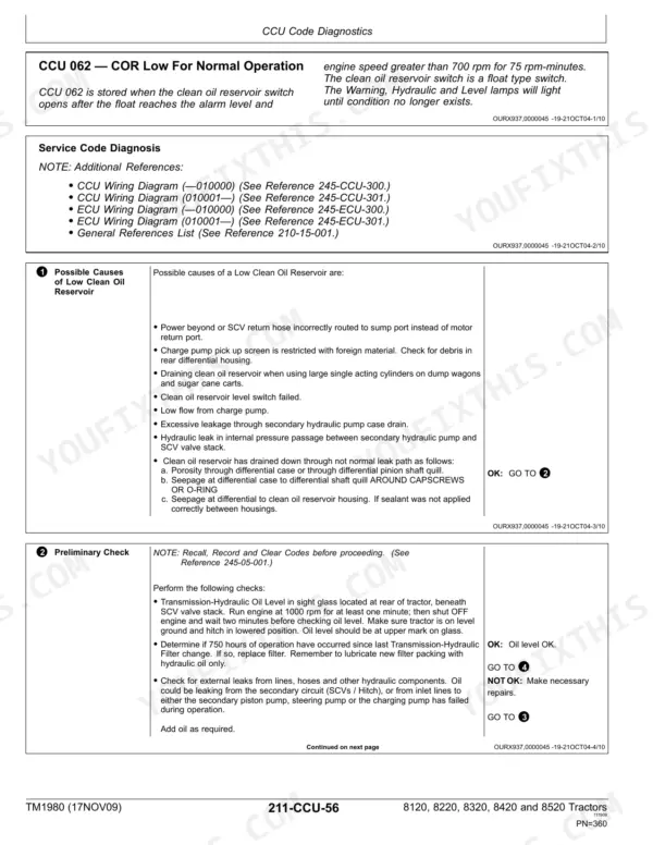
Manual Section: System Diagnosis p. 1073CCU code 5 - engine oil pressure input out of range low
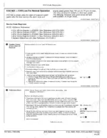
The Service Codes section pairs this code with a real pressure check before you condemn the sensor: minimum 138 kPa (20 psi) at no-load idle, 400 kPa (58 psi) operating spec. If actual pressure checks good, the diagnostic procedure walks the sensor circuit; if not, you have an engine problem, not an electrical one.
Manual Section: Service Codes p. 1444Hitch will not raise or lower from the rear fender switch, or drops too slowly
The Observable Symptoms charts cover a dead hitch step by step: fuses, the raise/lower switch, connector and harness continuity, then the lever and hitch position sensor circuits behind codes ACU 53-57. For slow drop, the manual covers rate-of-drop adjustment before you go hunting internal circuit leakage.
Manual Section: Observable Symptoms p. 842Frequently Asked Questions
What does error code ACU 41 mean on a John Deere 8420, and how do I fix it?
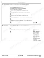
ACU 41 flags intermittent electrical power to the armrest control unit. The manual's Service Codes and Electrical sections walk you through checking the armrest power feed, connectors and harness with pin-by-pin diagnostics rather than guessing at modules. Most ACU 41 cases trace to a loose connector or chafed harness under the armrest, not a dead controller.
How do I reset ACU 2 (VMD calibration) or ACU 3 (hitch/throttle calibration) codes?
These codes clear by performing the calibration procedure, not by pulling a fuse. The Control Units section covers the calibration steps for the armrest control unit, including hitch and hand throttle calibration, plus the address-and-code readout on the corner post display so you can confirm the code is actually gone.
Does this manual have engine head bolt torque specs and overhaul procedures?
No, and I'd rather tell you straight than sell you the wrong book. This is the Operation and Test volume: diagnostics, service codes, pressure tests, adjustments and schematics. Assembly torques, engine teardown and component overhaul live in the companion Repair technical manual for these same models. If you're diagnosing, buy this one; if you're rebuilding, you need both.
My hydraulics quit entirely or the oil runs hot. Will this manual help me find the cause?
Yes, that's exactly what it's for. The System Diagnosis and Hydraulic System sections give you a test sequence with real numbers: standby pressure 30-40 bar, stall 196-210 bar, oil cooler differential pressure by temperature. Total loss usually comes back to low oil, plugged filters or the charge pump suction screen; overheating points at a clogged filter element or internal leakage. The tests tell you which before you start replacing parts. p. 1157
Which controllers and codes does it cover - CCU, ACU, PCU?
All of them. The Service Codes section lists codes by controller: CCU (chassis, including CODE 5 for low engine oil pressure input and CODE 7 for ECU/tractor model mismatch), ACU (armrest, codes like 41, 49, 53-57 and 70 for the IMS switch), PCU for the powershift, plus the engine ECU. Each code gets a diagnostic procedure, not just a definition. p. 1444







