
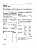
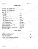
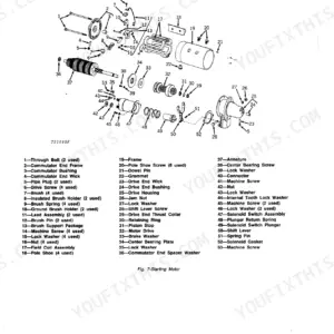
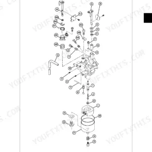
Part of the John Deere Repair Manuals.
This 435-page John Deere JD500-C Technical Manual covers every system on your Loader Backhoe, from the Group 15 hydraulic pump down to the Extendible Dipperstick. You get complete electrical schematics with wire harness connector routing, full hydraulic system diagnosis charts, and a dedicated troubleshooting section for slow hydraulics and power train faults, plus torque values for the loader frame, boom, and bucket assemblies. The specs are grounded: tighten oil pressure regulating valve housing bolts to 45 ft-lbs, and expect 175 ± 10 psi at operating oil pressure. Your interrupter valve spring should free-length at 1.44 inch. No more chasing wiring faults with a multimeter and a prayer. Bookmarked by section so you jump straight from Engine to Hydraulic System without scrolling, and it opens clean on a tablet right at the machine.
What's Inside This John Deere JD500-C Manual
| System | Pages | Key Topics |
|---|---|---|
| General | 7-50 | Specifications, Predelivery, Delivery, And After-Sale Services (Predelivery Service, Delivery Service, After-Sale Inspection) |
| Engine | 51-84 | Diagnosis (Diagnosing Malfunctions) |
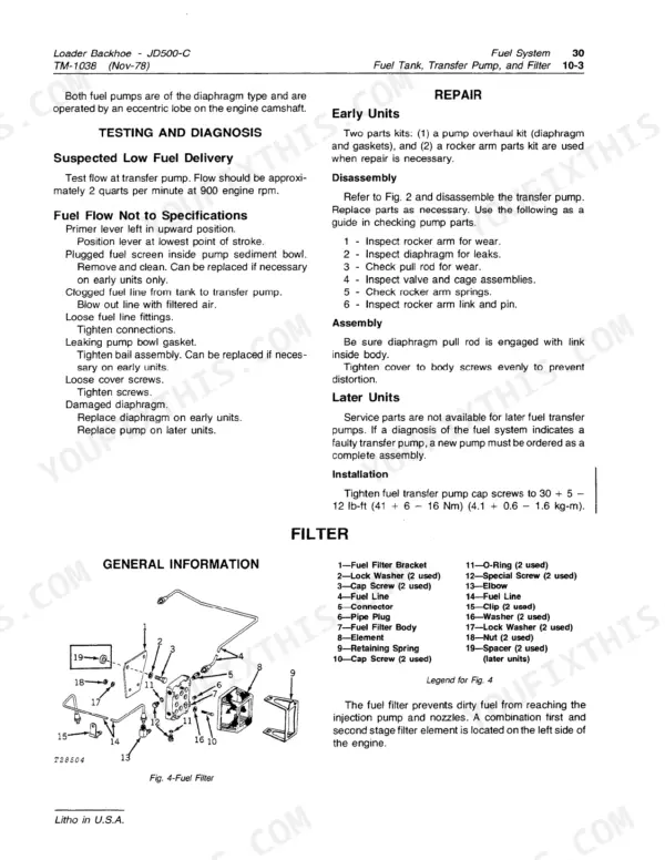
| Fuel System | 85-99 | Diagnosis (Diagnosing Fuel System Malfunctions), Fuel Tank, Transfer Pump, And Filter (Specifications), Air Intake System (Air Cleaner) |
| Electrical System | 100-129 | Wiring Diagrams (Removing Body Connectors From Wires, Electrical Schematics, Wiring Routing, Wire Harness Connectors, Miscellaneous Equipment Routing) |
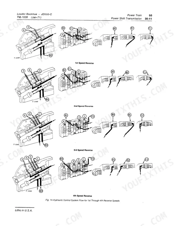
| Power Train | 130-196 | Diagnosis (Diagnosing System Malfunctions) |
| Steering and Brakes | 197-198 | General Information, Power Steering Cylinder and Valve, Steering Column, Brake Pedals and Linkage, Brake Valve, Bleeding |
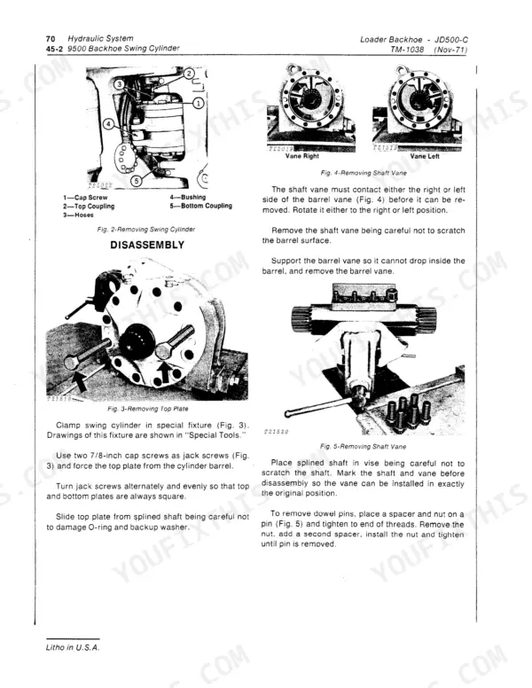
| Hydraulic System | 199-295 | System Testing (Symptom Index, Test and Adjustment, System Test, Function Leakage Test, Cylinder Leakage Test, Transmission Pump Test, Standby Pressure Test, Pressure Control Valve Test, Brake Valve Leakage Test, Differential Lock Valve Pressure Test, Transmission Pressure Test, Transmission Lube Pressure Test, Specifications, List of Parts for Tests, Special Tools) |
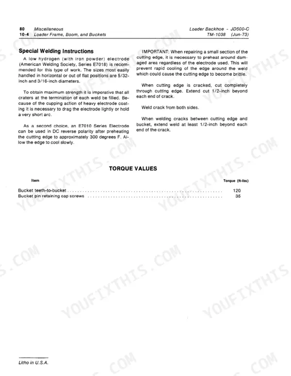
| Miscellaneous | 296-322 | Front Axle and Pivot Bracket (Removal, Repair, Installation, Adjustment, Specifications), Loader Frame, Boom, And Buckets (Repair, Torque Values) |
| Component Repair Illustrations | 323-429 | Power Steering Cylinder and Valve, Loader Control Valve and Linkage, Hydraulic Component Breakdowns, Exploded Views, Assembly References |
| Alphabetical Index | 430-435 | Index of Sections, Groups and Procedures |
Quick Reference Specifications
| Specification | Value | Page |
|---|---|---|
| Throttle shaft lever turns | 1/4 in. | p. 30 |
| oil pressure regulating valve housing mounting bolts torque | 45 ft-lbs | p. 213 |
| Oil pressure | 175 ± 10 psi | p. 229 |
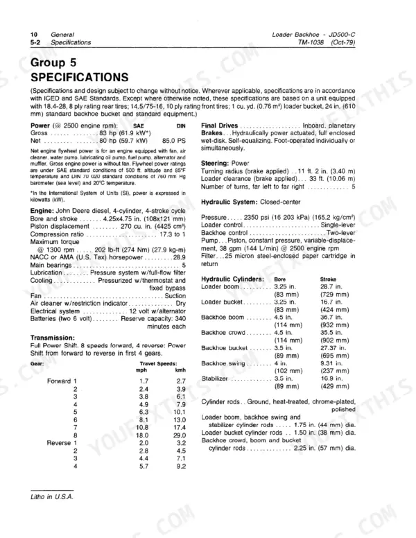
| Engine Displacement | 270 cu. in. (4425 cm³) | p. 8 |
| Hydraulic System Capacity | 21.5 gal. | p. 9 |
| Loader Bucket Capacity (Heaped) | 1 cu. yd. (0.76 m³) | p. 9 |
| Backhoe Digging Depth (ICED) | 15 ft. 1 in. (4.60 m) | p. 9 |
John Deere JD500-C Common Problems This Manual Covers
John Deere JD500-C shows no forward movement in gears 1 through 4 despite normal shift lever feel
Check the transmission control linkage adjustment first before splitting the case. Inspect the park control lever pivot for excess play; maximum allowable end play is 0.030 inch per page 228. Confirm the neutral start switch is tightened to 20 to 25 lb-ft. If linkage and switch check out, pressure-test the transmission control valve for internal failure.
Manual Section: Power Train p. 130Weak or non-functional hydraulics across loader, backhoe, and steering functions with engine running normally
Run the hydraulic system test outlined on page 275; these general complaints have many possible causes. Verify oil pressure reads 175 ± 10 psi as documented on page 229. Check hydraulic reservoir level meets the 21.5 gallon system capacity noted on page 9. If pressure stays low, pull the pump and inspect for worn gears or a cracked housing.
Manual Section: Hydraulic System p. 199Alternator chirping noise followed by starting circuit failure and no crank on ignition
Check the charging and starting circuit diagnosis procedures beginning on page 100. Inspect the alternator bearing for play or noise under load; a chirp usually signals bearing wear before the unit shorts internally. Test battery voltage at idle and at 1900 rpm, and inspect wiring harness connectors for corrosion before replacing the alternator.
Manual Section: Electrical System p. 100Unusual grinding or clicking noises inside the axles with a noticeable loss of braking power
Check the power brakes malfunction procedures starting on page 197. Bleed the brake system and inspect the accumulator for proper charge before condemning internal axle components. Listen for chatter during pedal application; internal brake disc wear is a high-cost repair, so confirm fluid contamination or seal failure first with a pressure and leakage check.
Manual Section: Steering and Brakes p. 197Loader and backhoe control valve sticking or leaking with excessive wheel play at the pins
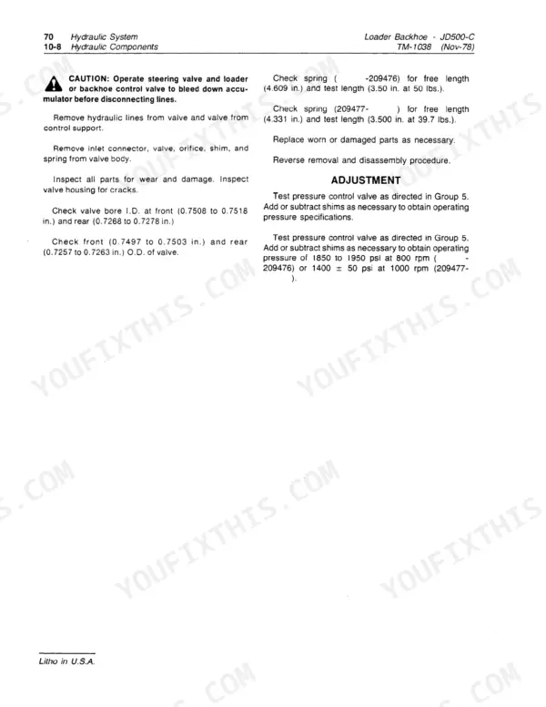
Inspect the interrupter valve in the control valve housing for free movement; spring free length should measure 1.44 inch per page 215. Clean or rebuild the valve if it sticks in the bore. Check wheel pins and bushings for wear beyond spec, and replace both together since mismatched wear accelerates future play.
Manual Section: Hydraulic System p. 215Frequently Asked Questions
Where are the brake bleeder valves on a John Deere JD500-C?
The manual describes the procedure for bleeding brakes, indicating that bleed screws are part of the brake system. To bleed, turn the bleed screws out two turns, start the engine, depress the brake pedals for two minutes, then tighten the bleed screws. If the pedal feels spongy, repeat the operation. A diagram of a bleed screw is shown in Fig. 8 on page 70-25-5. p. 263
How to fix play in the front right wheel on a John Deere JD500-C?
To address play in the front wheel, inspect the knuckle spindle bearing surface for excessive wear, checking if the O.D. of the inner bearing surface is between 2.2485 to 2.2495 inches and the outer bearing surface is between 1.4355 to 1.4365 inches. Compare thrust washers (28) with new washer size (0.167 to 0.173 inch). During installation, tighten the wheel on the hub to 275 ft-lbs or the bolts (51) to 100 ft-lbs. p. 300
How to clean or rebuild the hydraulic stroke control valve on a JD500-C?
To service the hydraulic stroke control valve, inspect it and the crankcase outlet valve (for early units) for foreign material or varnish build-up. If found, remove the varnish build-up using a crocus cloth. The manual explicitly states not to use lapping compound for removing varnish. p. 242
Does the John Deere JD500-C have digital error codes?
Based on the manual's publication dates (ranging from 1971 to 1980) and the diagnostic procedures described, the John Deere JD500-C does not appear to utilize digital error codes. Diagnostics rely on mechanical and electrical tests such as pressure readings, voltage checks, and visual inspections. p. 52
Where can I find the technical repair manual for a 1978 JD 500 C backhoe/loader?
The document you are currently viewing is the technical repair manual for the John Deere JD500-C Loader Backhoe. It contains detailed information for repair and maintenance, with various sections updated across different years, including revisions from 1978. p. 1
Is this John Deere JD500-C Technical Manual a digital download?
You get a 435-page searchable PDF that downloads instantly after checkout. Open it on your laptop, tablet, or phone, and bring it right to the shop floor.
Is this John Deere JD500-C Technical Manual printable?
Yes. Print the pages or sections you need for your own shop use. Any standard printer works.







Reviews
There are no reviews yet.