
Part of the Kubota Operator Manuals.
This is the Kubota LA535 front loader operator manual, 59 pages covering the safe operation, setup, and maintenance of the LA535 loader attachment. It documents the manufacturer procedures for mounting, running, removing, and storing the loader on a suitable tractor.
Inside you get the loader and bucket specification tables, dimensional and operational figures, pre-operation checks including tread setting and rear ballast, and the loader operating techniques for filling, dumping, and loading from a bank. Full mount and dismount sequences for both standard and Swift-Tach loaders are laid out step by step, along with the maintenance and lubrication schedule.
Owners and independent operators use this PDF to set up the LA535 correctly, torque the mounting hardware, purge the hydraulic system, and remove or reinstall the loader without guesswork.
What's Inside This Kubota LA535 Operator Manual
| System | Pages | Key Topics |
|---|---|---|
| Safe Operation | 7-12 | Precautions Before Operating the Loader (2-Lever Quick Coupler, Euro Quick Coupler), Precautions After Operating the Loader, Safety Labels, Care for Safety Labels |
| Servicing of the Loader | 13 | Dealer Service, Kubota Loader (Model, Serial Number, Date of Purchase, Name of Dealer, To Be Filled in by the Purchaser) |
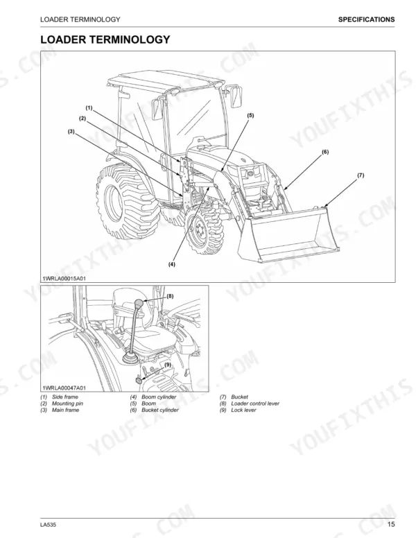
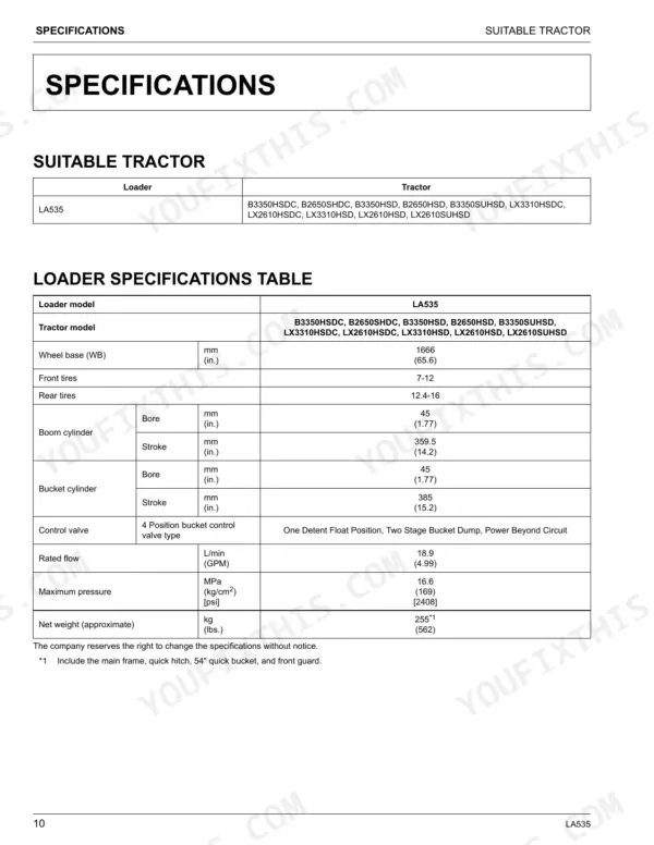
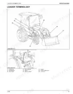
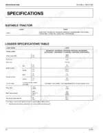
| Specifications | 14-19 | Suitable Tractor, Loader Specifications Table, Bucket Specifications Table, Dimensional Specifications, Operational Specifications, Loader Terminology |
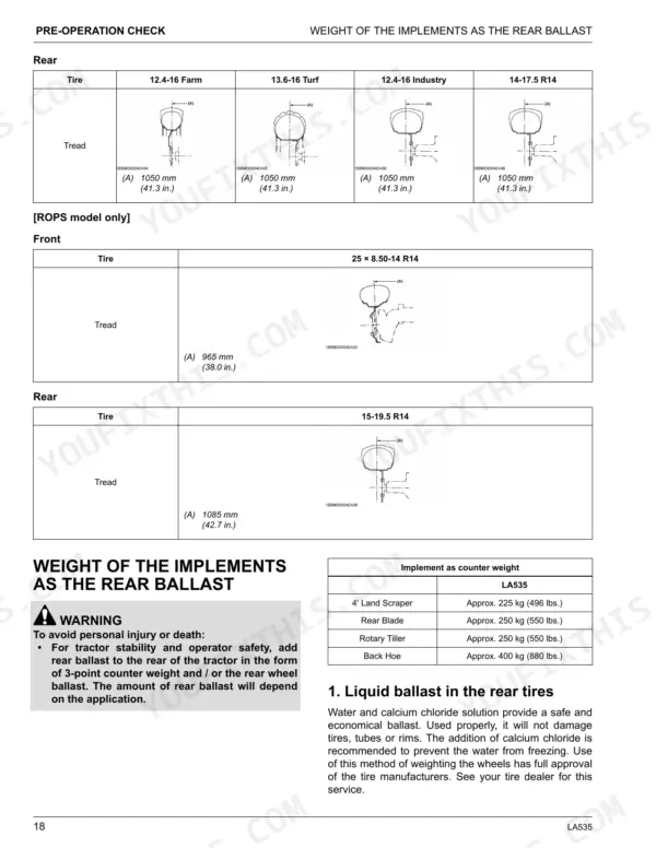
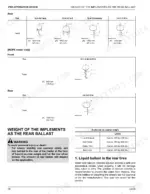
| Pre-Operation Check | 20-25 | Lubrication Before Operating the Loader, Checking the Transmission Fluid, Setting the Tread, Weight of the Implements As the Rear Ballast, Liquid Ballast in the Rear Tires |
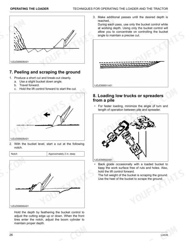
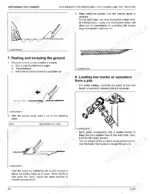
| Operating the Loader | 26-37 | Operation of the Loader, Techniques for Operating the Loader and the Tractor, Filling the Bucket, Dumping and Lowering the Bucket, Loading From a Bank |
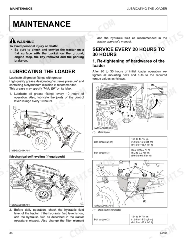
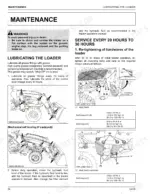
| Maintenance | 38-40 | Lubricating the Loader, Service Every 20 Hours to 30 Hours, Re-Tightening of Hardwares of the Loader, Re-Tightening of Hardwares of Mechanical Self Leveling [If Equipped] |
| Removing the Loader | 41-44 | How to Remove the Loader (Removing Non Swift-Tach Loader, Lift the Weight Off the Front Wheels with the Bucket, Stop the Engine, Remove the Mounting Pins From the Loader Main Frame and Store Them on Boom, Start the Engine and Run at Idle, Slowly Release All Hydraulic Pressure by Moving the Hydraulic Control Lever in All Directions, Disconnect the 4 Hoses with Quick Couplers at the Control Valve, Hook the Hoses on the Side Frame and Attach the Protective Plugs to Their Respective Couplers As Shown Below, Confirm the Following Points, Place the Protective Caps on the Quick Coupler Ends, Start the Engine and Slowly Back the Tractor Away From the Loader) |
| Storage of the Loader | 45 | Storing the Loader (Store the Loader in a Clean, Dry Place, Make Sure That the Loader Is Properly Supported, Check the Hydraulic Hoses and Connections, Repair or Replace Any Worn, Damaged, Or Missing Parts, Lubricate the Loader As Described on Lubricating the Loader on Page 34, Apply a Coat of Grease to All Exposed Cylinder Rods to Prevent Rust, Repaint Worn or Scratched Parts) |
| Reinstalling the Loader | 46-57 | How to Reinstall the Loader (Reinstalling Non Swift-Tach Loader, Start the Engine and Run at Idle, Slowly Move the Hydraulic Control Lever to Dump Position to Lower the Side Frames Into the Main Frames and Engage the Bosses of the Main Frames to the Guide Bosses of the Main Frames, Stop the Engine, Reinstall the Mounting Pins and Secure Them with the Locking Rods, Start the Engine, Raise the Boom Until the Stand CAN Be Rotated, Store the Stands to Their Original Positions and Secure Them with the Spring Pins As Shown, Lower the Boom and Level the Bucket, Reinstalling Swift-Tach Loader [If Equipped], Carefully Drive the Tractor Between the Side Frames of the Loader As Shown in the Following Figures, Set the Parking Brake and Unfasten the Seat Belt, Remove the Protective Caps From the Tractor Quick Coupler, Take Off the Dust Cap, Fold the Dust Cap, Leave Dust Cap Hanging, Align the Quick Coupler with the Bottom Side Quick Coupler on Tractor and Rotate the Lever Down Until the Quick Coupler Locks, Make Sure That the Mounting Levers of Both Sides Are in the Lock Position As Shown in the Follow Figures, Fasten the Seat Belt and Start the Engine, Slowly Operate the Loader Control Lever to Roll the Bucket Back and Extend the Boom Cylinders Until the Left and Right Guide Bosses of Side Frames Contact the Main Frames, Slowly Operate the Loader Control Lever to the Dump Position to Lower the Side Frames Into the Main Frames, And Engage the Left and Right Guide Bosses of the Side Frames to the Saddle Bracket of the Main Frames, As Shown in the Following Figure, Make Sure That the Left and Right Bosses of the Side Frames Are Engaged by the Saddle Bracket of the Main Frames, Slowly Operate the Loader Control Lever to the Down Position to Lift the Front Wheels Slightly with the Loader Until the Mount Hooks Are Completely Mounted on the Main Frame As Shown in the Following Figure, Make Sure That the Stand Lever Is at Its Low Position As Shown in the Following Figure, Slowly Dump the Bucket Until the Stands Are in the Stowed Position, Using the Stand Lever Lock the Stands in the Stowed Position As Shown Below, Verify LH/RH Stand Hooks Are Engaged Properly As Shown Below) |
Quick Reference Specifications
| Specification | Value | Page |
|---|---|---|
| Loader mounting bolts torque | 124 to 147 N·m (12.6 to 15.0 kgf·m) (91.5 to 108.4 lbf·ft) for bolts (2) (4) and main frame connector bolt (2); 80.0 to 90.0 N·m (8.2 to 9.2 kgf·m) (59.0 to 66.4 lbf·ft) for bolt (3); 260 to 304 N·m (26.5 to 31.0 kgf·m) (192 to 224 lbf·ft) for Mechanical self leveling bolts (1) (2) (3) | p. 38 |
| Rated flow | 18.9 L/min (4.99 GPM) | p. 14 |
| Maximum pressure | 16.6 MPa (2408 psi) | p. 14 |
| Net weight (approximate) | 255 kg (562 lbs.) | p. 14 |
| Front tire inflation pressure (7-12, 4PR) | 170 kPa (24 psi) | p. 19 |
| Rear tire inflation pressure (12.4-16, 4PR) | 110 kPa (16 psi) | p. 19 |
| Raising time | 3.6 sec. | p. 17 |
| Lowering time | 2.3 sec. | p. 17 |
| Main frame bolt torque (2)(4) | 124 to 147 N·m (91.5 to 108.4 lbf·ft) | p. 34 |
| Mechanical self leveling bolt torque (1)(2)(3) | 260 to 304 N·m (192 to 224 lbf·ft) | p. 35 |
| Stand lever roller clearance | 1 to 2 mm (0.04 to 0.08 in.) | p. 53 |
| M10 Tightening torque (stand lever rod) | 39.2 to 45.1 N·m (28.9 to 33.2 lbf·ft) | p. 53 |
Kubota LA535 Common Problems This Manual Covers
Loader mounting bolts loosen over time
Vibration and load cycling back the mounting and self-leveling hardware off if it is not re-torqued on schedule. The maintenance section covers re-tightening the loader hardware, with mounting bolt torque of 124 to 147 N-m and self-leveling bolts at 260 to 304 N-m.
Manual Section: Maintenance p. 38Air trapped in the hydraulic system
Spongy or jerky boom and bucket movement after service usually means air is still in the lines. The pre-operation check section covers purging air from the hydraulic system before working the loader.
Manual Section: Pre-Operation Check p. 20Loader hard to remove or reinstall
Trapped hydraulic pressure or misaligned side frames make the loader difficult to detach or remount. The removing and reinstalling sections give the exact pressure-release and alignment steps, including releasing pressure through the control lever.
Manual Section: Removing the Loader p. 41Tractor rears or feels unstable with a load
Too little rear ballast lets the front end overload and the rear wheels lighten when lifting. The pre-operation check section covers rear ballast weight, liquid ballast in the rear tires, and tire inflation.
Manual Section: Pre-Operation Check p. 20Quick coupler leaks or will not seat
Dirty or unseated quick couplers cause leaks and lost function at the control valve connections. The removing section covers disconnecting, plugging, and capping the hydraulic hoses and couplers correctly.
Manual Section: Removing the Loader p. 41Worn or damaged loader left in storage
Storing the loader without lubrication and inspection lets cylinder rods rust and worn parts go unnoticed. The storage section covers greasing exposed rods, checking hoses and connections, and repairing worn parts.
Manual Section: Storage of the Loader p. 45Frequently Asked Questions
What does this manual cover?
It is the operator manual for the Kubota LA535 front loader, covering safe operation, specifications, pre-operation checks, operating techniques, maintenance, and mounting and dismounting the loader.
What is the torque for the loader mounting bolts?
The manual specifies 124 to 147 N-m (91.5 to 108.4 lbf-ft) for the main mounting bolts and 260 to 304 N-m (192 to 224 lbf-ft) for the mechanical self-leveling bolts. p. 38
Does it explain how to remove and reinstall the loader?
Yes. Separate sections walk through removing the loader, including releasing hydraulic pressure and capping couplers, and reinstalling both standard and Swift-Tach loaders step by step. p. 41
What are the loader hydraulic specs?
The specifications section lists a rated flow of 18.9 L/min (4.99 GPM) and a maximum pressure of 16.6 MPa (2408 psi), along with the loader net weight and cycle times. p. 14
How quickly can I access this Kubota LA535 manual after buying?
Immediate download of the complete 59-page searchable operator manual. Open it on any device: a laptop at your desk or a phone in the field.
Can I print pages of this Kubota LA535 manual for my own shop?
Yes. Print the pages or sections you need for your own shop use. Any standard printer works.






Reviews
There are no reviews yet.