
Part of the New Holland Operator Manuals.
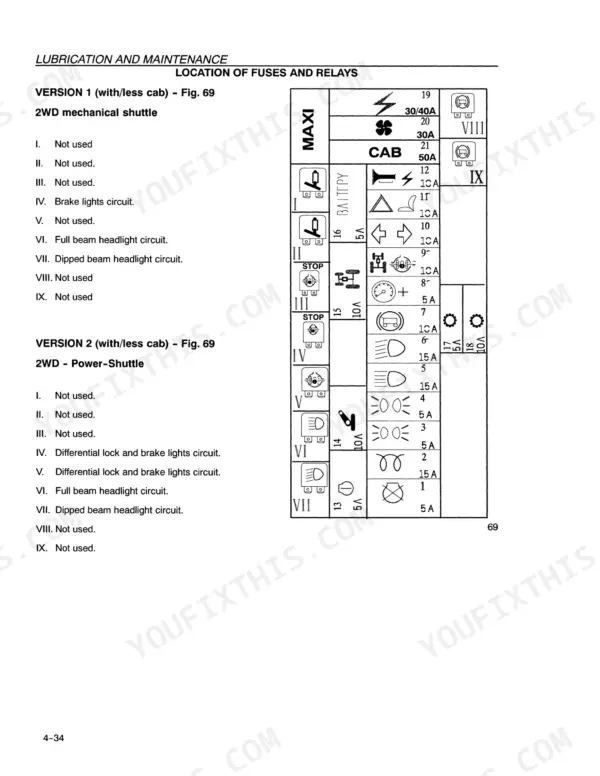
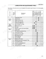
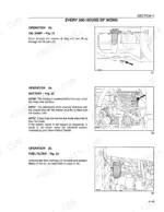
Running and servicing your tractor correctly, season after season, is what the New Holland TN70F, TN80F, TN95F operator manual PDF (OEM 86729781) packs into 216 pages. Its lubrication table runs from 10-hour daily checks through 50, 300 and 900 hours to 1200-hour annual and two-year jobs, and the warning light section tells you what each dash lamp means. Three-point linkage, PTO, rear remote valves, electro-hydraulic differential lock and 4WD get operating instructions, as do ballasting, tyre pressures and both transmissions: the 16F+16R mechanical shuttle and the 32F+16R Hi-Lo Power Shuttle. Clean the external air filter cartridge with compressed air below 5.9 bar, or wash it under 2.9 bar and dry below 50 °C; new oil filters go on 3/4 of a turn by hand. Bookmarked and searchable, the PDF rides along on a phone in the cab or a laptop in the shed.
What's Inside This New Holland TN70F, TN80F, TN95F Operator Manual
| System | Pages | Key Topics |
|---|---|---|
| General Information | 8-27 | Tractor Identification Plates, Important Ecological Considerations, Always Work Safely |
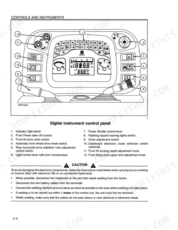
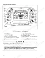
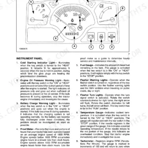
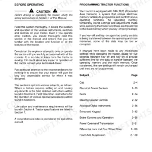
| Controls, Instruments and Operation | 28-71 | Before Using the Tractor (Control Panel with Digital Instrument, Operation Indicator Light Panel, Electronic Module) |
| Field Operation | 72-117 | Starting and Stopping (Brakes, Transmission Clutch Pedal, Electronically Controlled Electro-Hydraulic 4WD) |
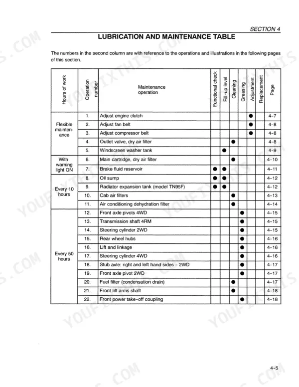
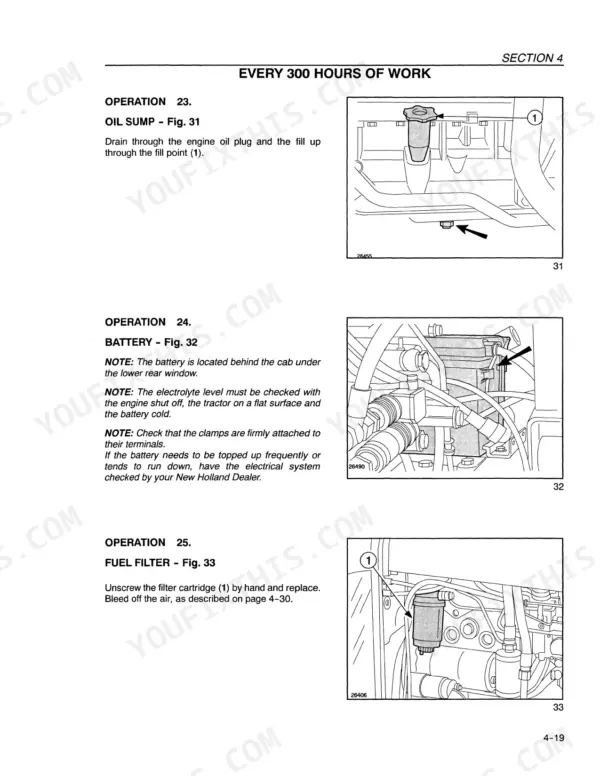
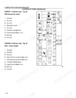
| Lubrication and Maintenance | 118-163 | Tractor Refuelling (Access for Inspection and Maintenance, Lubrication and Maintenance Table, Flexible Maintenance) |
| Troubleshooting, Causes and Solutions | 164-171 | Engine, Electrical System, Hydraulic System |
| Prolonged Tractor Inactivity | 172-173 | Rotary Injection Pump, Engine Oil, Air Filter Cartridge, Engine Cooling System, Battery, Fuel Tank |
| Accessories | 174-189 | Front Power Take-Off, Electronically Controlled Front Hydraulic Lift, Front Implement Three-Point Linkage |
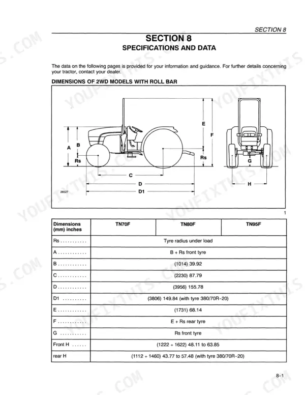
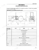
| Specifications and Data | 190-207 | Dimensions, Engine Specifications, Transmission Specifications |
| Inspections and/or Operations to Be Carried Out | 208-211 | Inflation Pressure, Air Filter, Cooling System Pipes, Coolant Level, Fuel Filter, Fan Alternator Compressor Belt, Engine Oil, Hydraulic Oil Filter |
Quick Reference Specifications
| Specification | Value | Page |
|---|---|---|
| Engine oil filter tightening | 3/4 of a turn by hand | p. 136 |
| Fuel filter screw tightening | 3/4 of a turn | p. 134 |
| Air filter (external cartridge) compressed air cleaning pressure | less than 5.9 bar (6 kg/cm²) | p. 127 |
| Air filter (external cartridge) water jet cleaning pressure | less than 2.9 bar (3 kg/cm²) | p. 127 |
| Transmission and services oil filter tightening | 3/4 of a turn by hand | p. 135 |
| Power-Shuttle/HI-LO oil filter tightening | 3/4 of a turn by hand | p. 137 |
| Fan belt tension (cab with air conditioning) | 16 mm with a load of 147 N (15 kg) | p. 125 |
| Battery charge level 100% | 12.66 V | p. 149 |
| Battery charge level 75% | 12.45 V | p. 149 |
| Maximum lift capacity at link ends (arms in position A) | 2660 lbs. (1207 kg) | p. 183 |
| Maximum lift capacity at link ends (arms in position B) | 3073 lbs. (1394 kg) | p. 183 |
| Engine Oil Capacity (without filter) | 9.5L | p. 162 |
New Holland TN70F, TN80F, TN95F Common Problems This Manual Covers
New Holland TN70F, TN80F, TN95F tractor engine will not start or is difficult to start
Check fuel level first, then confirm you are running fuel suited to the ambient temperature and engine oil of the right viscosity, per the chart on page 165. If air is in the fuel system, bleed it. Replace a clogged fuel filter element and unscrew the filter screw 3/4 of a turn as shown on page 134. Do not smoke near diesel fuel (page 119). A fuel injector fault means contact your dealer.
Manual Section: Engine Troubleshooting p. 165Engine overheating during field work with coolant temperature climbing under load
Check coolant only once the engine has cooled, using a cloth to slowly unscrew the cap and release pressure (page 21). Top up the expansion tank, look for leaks, clean a clogged radiator core and replace a defective cap, per page 166. Keeping hands clear of the fan and belts, check belt tension on page 125: 10 to 11 mm at 78 to 98 N, or 16 mm at 147 N with air conditioning.
Manual Section: Engine Troubleshooting p. 166Battery charge warning light stays on with the engine running and batteries not charging
Check idling speed first and increase it if low, since the chart on page 168 lists low idle as a cause. Inspect the belt tensioning device and replace a loose or worn belt, keeping hands clear of belts and rotating parts (page 21). Clean and tighten loose or corroded terminals, verify battery charge is at least 12.6 volts, then check electrolyte level and specific gravity. An alternator fault goes to your dealer.
Manual Section: Electrical System Troubleshooting p. 168Hydraulic fluid overheating and the hydraulic system not working properly during field work
Check fluid level per page 169 and top up if low or correct it if too high. Replace a clogged hydraulic filter, oiling the seals and screwing the container on by hand 3/4 of a turn (page 135). Set flow regulation to a lower capacity. Never alter relief valve calibration (page 14); pressurised oil leaks cause serious injuries (page 18). If the fault persists, contact your dealer.
Manual Section: Hydraulic System Troubleshooting p. 169Three-point linkage does not lift fully or hydraulic lift operates slowly in draft control
Adjust the link arm top limiter if the linkage stops short of full lift, per page 170. For slow draft control response, adjust the combined draft/position control and check implement settings; reduce load if the linkage is overloaded. If lowering stays too slow, have your dealer check the valves. Stay off the implement and tractor while the Lift-o-Matic control is operating (page 22), and never leave implements raised when stationary (page 18).
Manual Section: Hydraulic Lift and 3-Point Equipment Coupling Troubleshooting p. 170PTO will not engage and the PTO disengagement system shows a fault code
Check the code against the PTO disengagement table on page 177. Code 11 means the fuse F9 circuit is open or ECU pin 35 is disconnected; codes 15, 16 and 17 point to the solenoid valve terminals and wiring; code 18 points to a battery or alternator fault. Codes 37 and 38 mean contact your dealer. Disengage the PTO and shut off the engine before servicing (page 24), then get back in the field.
Manual Section: Power Take-Off Disengagement System Fault Codes p. 177Frequently Asked Questions
What are the fault codes for the Power Take-Off (PTO) disengagement system?
The manual provides a list of fault codes for the PTO disengagement system on page 177. For example, code 11 indicates a 'Fuse F9 circuit open' or 'Pin N° 35 on ECU disconnected', while code 15 indicates a 'Solenoid valve terminals short circuit'. p. 177
How do I interpret the fault code signals on the dashboard?
Fault codes are identified in six phases: 5 rapid flashes, a 2-second pause, n flashes for the first figure, a 1-second pause, n flashes for the second figure, and a 3-second pause. For example, code 21 is represented by 2 flashes for the first figure and 1 flash for the second figure (page 65). p. 65
What is the procedure for bleeding the fuel system?
To bleed the fuel system, unscrew the bleed plug (1) by two turns, move the lever (1) until fuel without air bubbles spurts out, and tighten the plug. Then, unscrew the injector connectors, turn the starter motor until fuel flows without air bubbles, and reconnect (page 147). p. 147
What is the correct engine oil filter replacement procedure?
When replacing the engine oil filter (1), oil the seal, screw it on, and tighten the cartridge 3/4 of a turn by hand (page 138). p. 138
What is the specified valve clearance for the New Holland TN70F, TN80F, TN95F engine?
The valve clearance for inlet and exhaust valves, when the engine is cold, is 0.012 ± 0.002 inches (0.30 ± 0.05 mm) (page 141). p. 141
Will this New Holland TN70F Operator Manual download right away?
One searchable PDF covering 216 pages, delivered instantly. No disc, no shipping, no waiting on the post.
Am I free to print this New Holland TN70F Operator Manual?
Yes. Print the sections you need to take out to the shop for your own use. Standard letter or A4 paper works.





Reviews
There are no reviews yet.