
Part of the John Deere Repair Manuals.
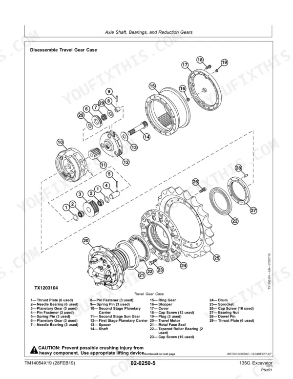
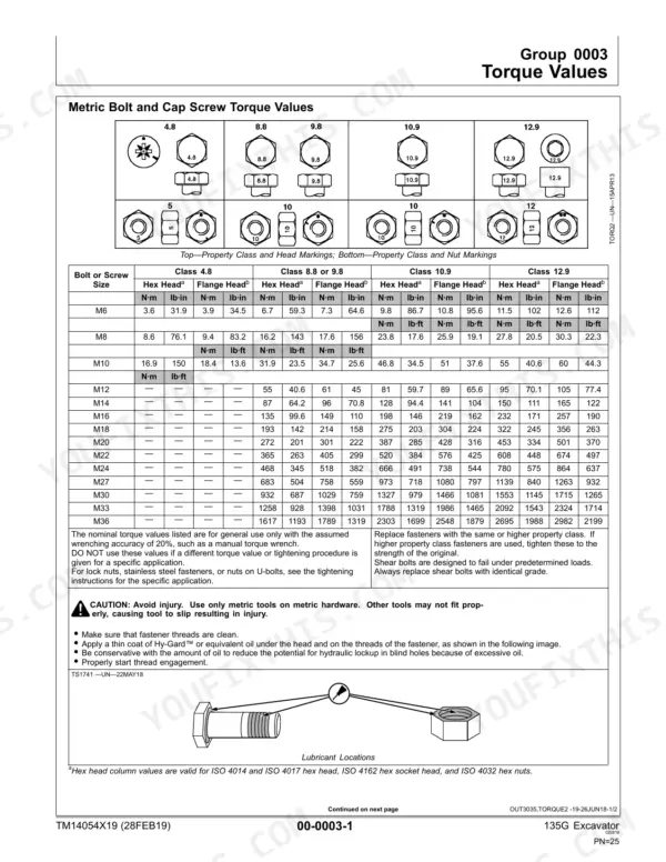
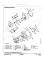
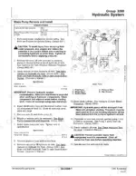
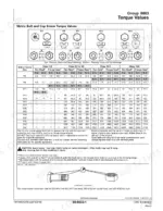
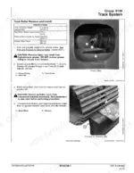
The travel motor is weeping oil and the crew is parked until you get it apart. Answering that is the 490-page John Deere 135G repair manual PDF, factory document TM14054X19, the Repair Manual written for this excavator. Repair procedures for the swing motor, travel motor and the rest of the machine fill the longest stretch of the book, every teardown carried through to its final torque figure. Exploded views break the track chain, idler, final drive and swing gear case down to the bushing, and torque charts cover metric and inch hardware from 3.6 N·m up to 2982 N·m. Refill the hydraulic oil tank with 60 L (15.9 gal) and the cooling system with 21 L (5.5 gal); solenoid valve cap screws pull 6 N·m (53 lb·in) at the manifold. Guessing at swing bearing hardware costs you a day. Bookmarked and text searchable, and the printed pages can sit on the bench and get greasy.
Complete the set for your 135G
- Parts Catalog: John Deere 135G Parts Manual
What's Inside This John Deere 135G Manual
| System | Pages | Key Topics |
|---|---|---|
| General Information | 5-46 | Safety, Torque Values |
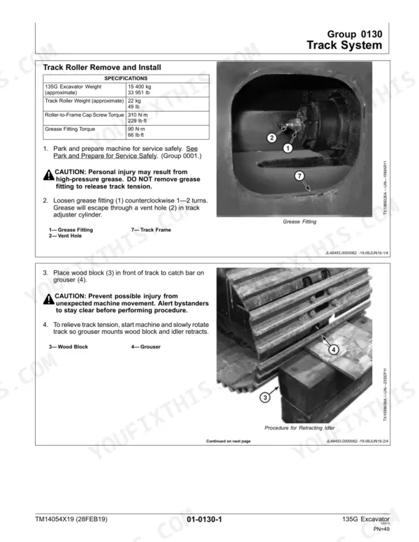
| Tracks | 47-84 | Track System |
| Axles, Differentials, and Suspension Systems | 85-106 | Travel Gear Case, Travel Motor and Park Brake |
| Engine | 107-118 | Removal and Installation |
| Engine Auxiliary System | 119-162 | Cooling Systems, External Exhaust Systems, External Fuel Supply Systems |
| Damper Drive (Flex Coupling) | 163-166 | Elements |
| Frame or Supporting Structure | 167-172 | Frame Installation, Chassis Weights |
| Operator's Station | 173-232 | Removal and Installation, Operator Enclosure, Seat and Seat Belt, Heating and Air Conditioning |
| Sheet Metal | 233-236 | Hood and Engine Side Shields |
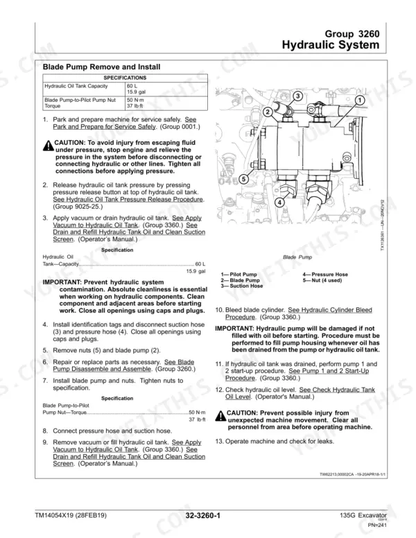
| Blade (If Equipped) | 237-260 | Blades, Hydraulic System |
| Excavator | 261-418 | Buckets, Frames, Hydraulic System |
| Swing or Pivoting System | 419-464 | Mechanical Drive Elements, Hydraulic System |
| Dealer Fabricated Tools | 465-490 | Lift Bracket, Track Recoil Spring Tool, Travel Gear Case Nut Wrench, Center Joint Lifting Tool, Swing Gear Case Nut Spanner Wrench |
Quick Reference Specifications
| Specification | Value | Page |
|---|---|---|
| Metric Bolt and Cap Screw Torque Values | M6 Class 4.8 Hex Head 3.6 N·m (31.9 lb·in) to M36 Class 12.9 Flange Head 2982 N·m (2199 lb·ft) | p. 25 |
| Unified Inch Bolt and Cap Screw Torque Values | 1/4 SAE Grade 1 Hex Head 3.1 N·m (27.3 lb·in) to 1-1/2 SAE Grade 8 Flange Head 2962 N·m (2185 lb·ft) | p. 27 |
| Cooling System Capacity | 21 L (5.5 gal) | p. 124 |
| Hydraulic Oil Tank Capacity | 60 L (15.9 gal) | p. 124 |
| Solenoid Valve-to-Manifold Cap Screw Torque | 6 N·m (53 lb·in) | p. 316 |
| 135G Excavator Weight (approximate) | 15 400 kg | p. 49 |
| Track Roller Weight (approximate) | 22 kg | p. 49 |
| Roller-to-Frame Cap Screw Torque | 310 N·m | p. 49 |
| Grease Fitting Torque | 90 N·m | p. 49 |
| Track Adjuster and Recoil Spring Weight (approximate) | 60 kg | p. 77 |
| Cap Screw Torque (Sprocket) | 270 N·m | p. 72 |
| Front Idler Weight (approximate) | 82 kg | p. 74 |
John Deere 135G Common Problems This Manual Covers
John Deere 135G hydraulic functions go slow and weak once the oil warms up
Check hydraulic oil level first: the tank holds 60 L (15.9 gal) per the capacity data on page 124. Clean packed debris from the oil cooler core and verify fan operation in the cooling system repair procedures. If flow stays low, inspect the flow limit solenoid and torque its manifold cap screws to 6 N·m (53 lb·in).
Manual Section: Cooling System Repair p. 124No hydraulic functions at all, or everything drops out intermittently right after startup
Test the main relay and check every ground and connector at the controller harness before condemning parts. Pull the pilot shutoff solenoid valve and confirm it opens. When reassembling the pilot plate, torque the cap screws to 50 N·m (37 lb·ft) as listed on page 381, and reseat the check valve plug at 15 N·m (133 lb·in).
Manual Section: Hydraulic System Repair p. 381Machine mistracks, pulls to one side, travel is jerky or low on power
Measure track sag on both sides and adjust the track adjuster before tearing into the travel motor. Inspect the track chain, front idler, and rollers for seized bearings. Replace worn rollers (22 kg each) and torque roller-to-frame cap screws to 310 N·m, grease fittings to 90 N·m, per the service data on page 49.
Manual Section: Track System Repair p. 49Engine cranks but will not start, no common rail pumping pressure
Prime the fuel transfer pump and bleed the supply line before chasing sensors. Check the crank position sensor air gap and its connector for corrosion. If you pull the engine to reach the rail components, rig for the 347 kg engine weight shown on page 109 and follow the removal sequence in the engine section.
Manual Section: Engine Removal and Installation p. 109Hydraulic oil overheats under combined dig and travel work
Drain and refill the cooling system to its 21 L (5.5 gal) capacity, then blow out the radiator, charge air cooler, and hydraulic oil cooler fins from the fan side. Inspect the fan drive and shroud seals. Verify the main relief is not weeping across, and confirm the 60 L hydraulic tank sits at full cold level.
Manual Section: Cooling System Repair p. 124Swing is sluggish or the boom and arm cylinders drift down under load
Cycle each function and watch for cylinder drift with the boom held at half height. Rebuild leaking boom or arm cylinders in the hydraulic system procedures, and inspect the swing bearing for rough spots. Torque load check valve plugs in the control valve to 15 N·m (133 lb·in) as specified on page 382 during reassembly.
Manual Section: Hydraulic System Repair p. 382Frequently Asked Questions
What is the torque specification for the John Deere 135G track roller bolts?
The torque specification for the roller-to-frame cap screws on the John Deere 135G is 310 N·m (229 lb·ft). p. 49
What is the torque specification for the John Deere 135G bucket pin bolts?
The initial torque for the shoe-to-link cap screws is 136 N·m (100 lb·ft), and the final torque is 411 N·m (303 lb·ft). p. 57
What is the oil capacity for the track roller on the John Deere 135G?
The oil capacity for the track roller on the John Deere 135G is 250 mL (8.5 fl oz). p. 51
What is the torque spec for the swing gear case-to-upperstructure cap screws on a John Deere 135G excavator?
The torque specification for the swing gear case-to-upperstructure cap screws is 500 N·m (369 lb·ft). p. 421
What is the hydraulic oil tank capacity for the John Deere 135G?
The hydraulic oil tank capacity for the John Deere 135G is 60 L (15.9 gal). p. 87
Is this John Deere 135G manual a download or a disc?
A 490-page Service Manual in searchable PDF format, available the moment you complete checkout. View on computer, tablet, or phone, with no shipping wait.
Is this John Deere 135G Service Manual printable?
Yes. Print the sections you need to take out to the shop for your own use. Standard letter or A4 paper works.








Reviews
There are no reviews yet.