
Part of the John Deere Repair Manuals.
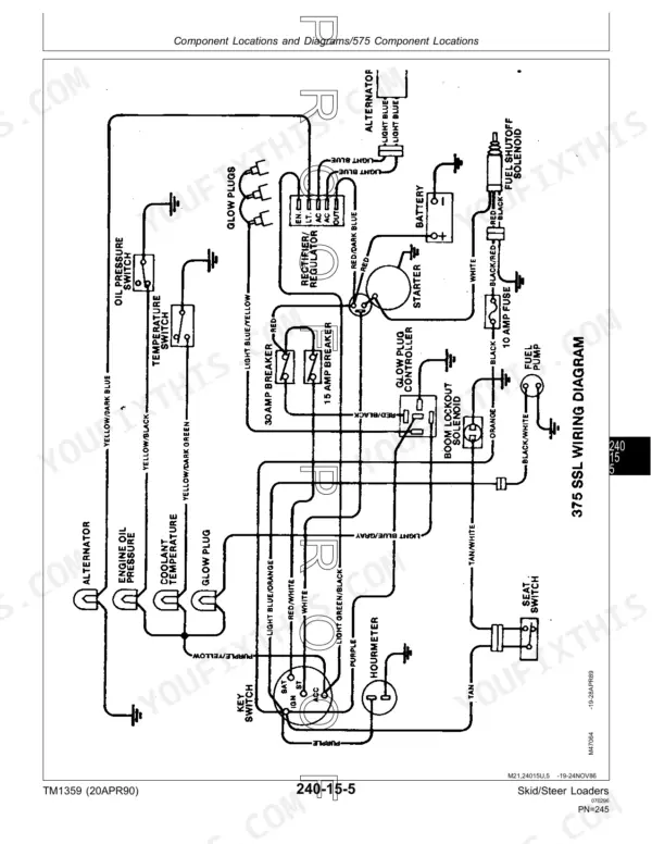
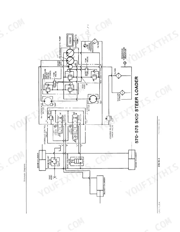
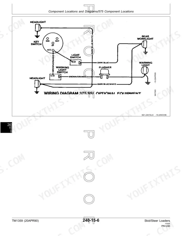
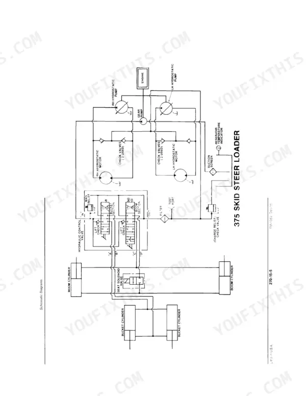
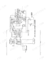
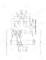
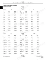
A hydrostatic pump that creeps in neutral strands a loader mid pile, and TM1359, the 540-page John Deere 375, 570, 575 Technical Manual PDF, is where that fix starts for all three skid-steers. Wiring diagrams trace circuits from the seat lockout switch back through the alternator and starter, and the schematic diagrams closing the hydraulic test section show where charge and relief pressure move through the main control valve. Diagnosis and checkout routines for the engine, power train, electrical and hydraulic systems fill better than a fifth of the book, each ending in a number you can measure rather than a guess. Change the fuel filter every 100 hours, and torque the charge pump shaft coupling to 51 to 58 N·m (38 to 43 lb-ft). Nobody answers the shop phone at seven on a Friday night. Bookmarked and searchable by text, it is bought once and stays yours as long as you own the loader.
What's Inside This John Deere 570, 575, 375 Manual
| System | Pages | Key Topics |
|---|---|---|
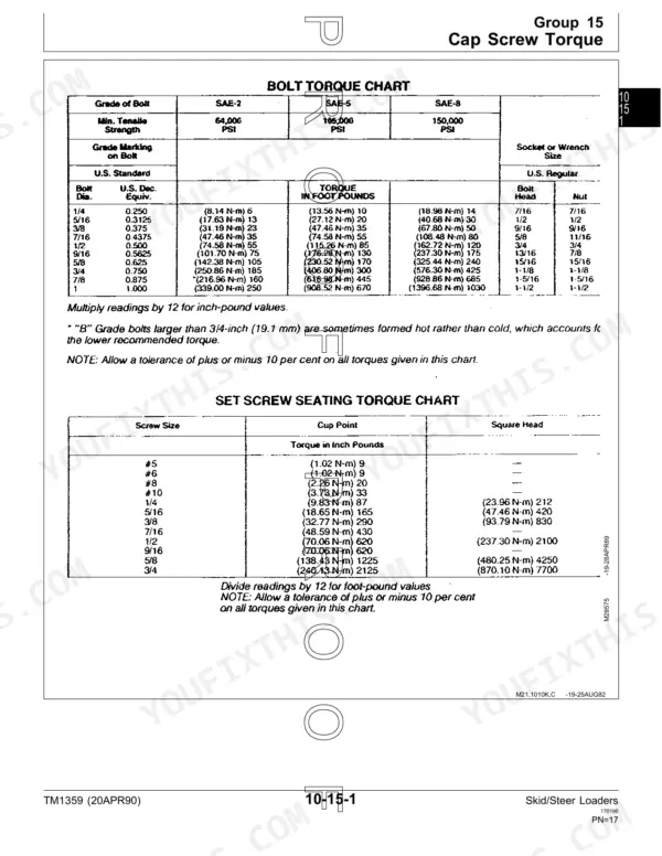
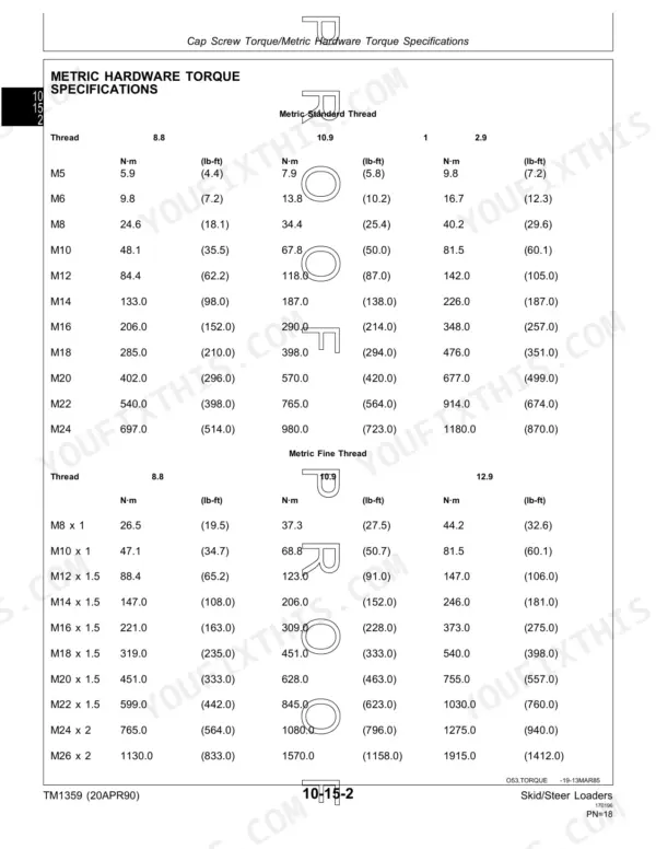
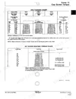
| General Information | 5-34 | Introduction and Safety, Cap Screw Torque, Tune-Up, Fuel and Lubrication, 570, 575 and 375, Serial Numbers |
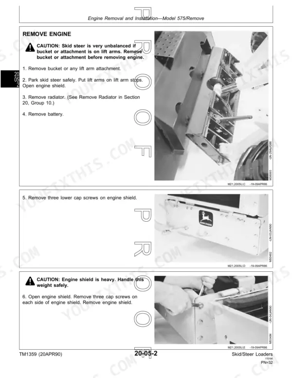
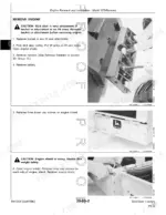
| Diesel Engine | 35-64 | Engine Removal and Installation, Model 575, Engine Removal and Installation Model 375, Cooling System |
| Gasoline Engine | 65-192 | Gasoline Engine Removal and Installation, Valve Actuating Means and Camshaft, Manifold, Cylinder Heads and Valves, Flywheel and Housing, Connecting Rods and Pistons |
| Fuel and Air System, Diesel | 193-208 | Throttle Control Linkage, External Fuel Supply |
| Fuel and Air System (Gasoline) | 209-224 | Carburetor, Carburetor and Governor Linkages, External Fuel Supply |
| Electrical | 225-242 | Alternator Model 570, Starter Model 570, Seat Lockout Switch |
| Power Train | 243-358 | Hydrostatic Pumps, Models 570 and 575, Hydrostatic Pump, Model 375, Hydrostatic Motors |
| Steering and Brakes | 359-370 | Park Brake, Steering Neutralizer |
| Hydraulics | 371-424 | Hydraulic Pump, Models 570 and 575, Model 375, Main Control Valve, Hydraulic Cylinders, Miscellaneous Hydraulics, Lift Arms |
| Specifications/Operational Checkout | 425-434 | Test and Adjustment Specifications, Machine Operational Checkout |
| Engine Operation and Tests | 435-468 | Engine System Checkout 375/575, Engine System Checkout 570, Engine System Diagnosis 375/575, Engine System Diagnosis 570 |
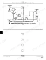
| Electrical Operation and Tests | 469-504 | Electrical System Checkout, Electrical System Diagnosis, Component Locations and Diagrams |
| Power Train Operation and Tests | 505-524 | Power Train System Checkout, Power Train Tests and Adjustments |
| Hydraulic Operation and Test | 525-540 | Hydraulic System Checkout, Hydraulic System Tests, Schematic Diagrams |
Quick Reference Specifications
| Specification | Value | Page |
|---|---|---|
| All Models | ||
| Fuel filter change interval | every 100 hours | p. 29 |
| Hydraulic Charge Pump Shaft Coupling Torque | 51—58 N·m (38—43 lb-ft) | p. 51 |
| Relief Valve Plug Torque | 78—80 N·m (55—60 lb-ft) | p. 246 |
| Charge Pump Pressure | 552—896 kPa (80—130 psi) | p. 430 |
| Delivery valve fitting torque | 42 N·m (369 lb-in.) | p. 452 |
| Charge pressure | 552—896 kPa (80—130 psi) | p. 513 |
| 570 | ||
| Starter mounting cap screws torque | 47 N·m (35 lb-ft) | p. 239 |
| 570 Engine Oil Capacity with filter | 4.7 L (5 qt) | p. 15 |
| 570 Fuel Tank Capacity | 38 L (10 gal) | p. 15 |
| 375 | ||
| Hydraulic pump shaft coupling cap screw torque | 51—58 N·m (38—43 lb-ft) | p. 385 |
| Starter Amp Draw Test (Maximum) | 200 amps at 300 rpm | p. 429 |
| Starter No-Load RPM Test (Minimum) | 9000 rpm | p. 429 |
John Deere 570, 575, 375 Common Problems This Manual Covers
John Deere 575 skid-steer won't start, cranks slow or clicks at the starter relay
Check the starting circuit tests in the electrical diagnosis section before condemning parts. Clean the battery terminals and cables, then run the starter amp draw test. Draw over 200 amps at 300 rpm means a dragging starter. If fuel delivery is suspect, pull the fuel filter; the interval listed on page 29 is every 100 hours.
Manual Section: Electrical System Diagnosis p. 429Boom and bucket will not move, lift arms dead with engine running normally
Sit down and buckle the seat belt, then cycle the key so the seat switch and boom lockout arm in the right order. Release the park brake switch and verify power reaches the port-lock solenoid using the wiring diagram on page 499. Confirm main relief holds 13 790 kPa (2000 psi) on the 575 before pulling the loader valve.
Manual Section: Hydraulic System Checkout p. 527Weak drive performance, machine creeps or stalls under load pushing into a pile
Warm the hydraulic oil first, then tee a gauge into the charge port. Charge pressure must read 552 to 896 kPa (80 to 130 psi) per page 513. Low reading means low reservoir oil, plugged charge lines, or a tired charge pressure relief valve. Torque the relief valve plug to 78 to 80 N.m (55 to 60 lb-ft) on reassembly.
Manual Section: Power Train Tests and Adjustments p. 513Hydraulic pump whining or screaming loud at idle, drive motors surging
Check the reservoir level and oil viscosity first, then pull the reservoir vent cap and clean it. Spray the pump inlet fittings with oil while it whines; if the noise drops, you found the air leak. Inspect the pump shaft coupling and torque the coupling cap screws to 51 to 58 N.m (38 to 43 lb-ft) per page 385 on the 375.
Manual Section: Hydraulics p. 371Bucket drifts down overnight and boom settles with the quick-attach plate loaded
Run the boom drift and bucket drift checks in the hydraulic checkout section starting on page 527. Park level, raise the boom, then time the settle with the engine off. Verify boom float is fully disengaged and the boom lock solenoid drops out. If drift stays, rebuild the bucket cylinders and retest system relief at 13 790 kPa (2000 psi).
Manual Section: Hydraulic System Checkout p. 527Engine surges, stalls under load and blows black smoke during hard cycles
Drain a fuel sample and check for water or wrong fuel before touching the injectors. Replace the fuel filter, keeping to the 100 hour interval, then bleed the lines and check for air. Pop test the injectors and torque the delivery valve fitting to 42 N.m (369 lb-in.) per page 452. Recheck engine oil level against the 6.4 qt (6 L) capacity on the 575.
Manual Section: Engine System Diagnosis 375/575 p. 452Frequently Asked Questions
What are the torque specifications for the John Deere 375 wheel lug bolts?
The wheel lug bolts for the John Deere 375 skid-steer loader should be tightened to a torque of 80 N·m (60 lb-ft). p. 339
What are the replacement specifications for the fuel filter on the 375 and 575 models?
If the fuel sulfur content is more than 0.5 percent, you must change the engine oil and filter every 100 hours. For maximum filter life, sediment and water should not exceed 0.10 percent. p. 29
What is the intake valve clearance for the 570 skid-steer loader?
The intake valve clearance for the 570 skid-steer loader is 0.35 mm (0.014 in.) when cold. p. 23
What is the correct engine oil pressure for the 570 skid-steer loader?
The engine oil pressure for the 570 skid-steer loader should be between 276 and 448 kPa (40 to 65 psi). p. 23
What is the correct cylinder head cap screw torque for the gasoline engine in a John Deere 570, 575, 375 skid steer?
The cylinder head cap screws should be tightened in sequence to 59—63 N·m (520—560 lb-in.) when lubricated. p. 99
Will this John Deere 375 Technical Manual download right away?
You get a 540-page searchable PDF that downloads instantly after checkout. Open it on your laptop, tablet, or phone, and bring it right to the shop floor.
Does this John Deere 375 manual allow printing?
Yes. Print a chapter or just the pages for the job at hand, for use in your own shop. Any home or office printer works.







Reviews
There are no reviews yet.