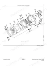
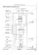
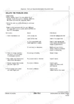

Part of the John Deere Repair Manuals.
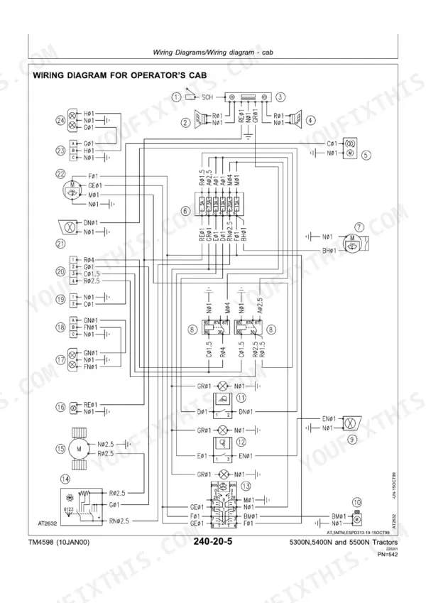
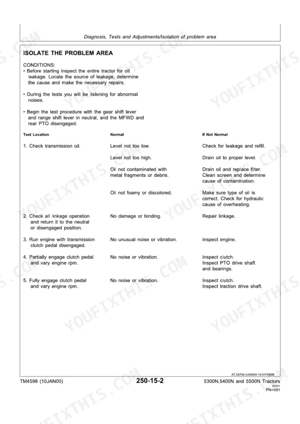
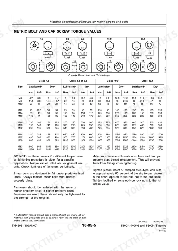
All 782 pages of this John Deere 5300N, 5400N, 5500N Technical Manual PDF (OEM TM4598) exist for one reason: putting factory data in your hands for these narrow tractors. You get complete wiring diagrams for the full electrical system, a hydraulic schematic tracing the open-center circuit, plus diagnosis and test procedures for the power train, three-point hitch, and front axle. Inside: metric cap screw torque tables, engine removal and installation steps, and test values for switches, sending units, and wiring harnesses. Torque the cap screws to 50 N·m (37 lb-ft) and fill the 5300N crankcase with 6 L of oil, filter included. No more chasing electrical gremlins with a test light and a hunch. Bookmarked PDF with a real text layer; jump to a section or search a spec, then get back under the hood.
What's Inside This John Deere 5300N, 5400N, 5500N Manual
| System | Pages | Key Topics |
|---|---|---|
| Safety | 5-20 | Recognize Safety Information, Follow Safety Instructions, Prevent Battery Explosions, Prevent Acid Burns, Avoid High-Pressure Fluids, Support Machine Properly, Service Tires Safely, Dispose of Waste Properly |
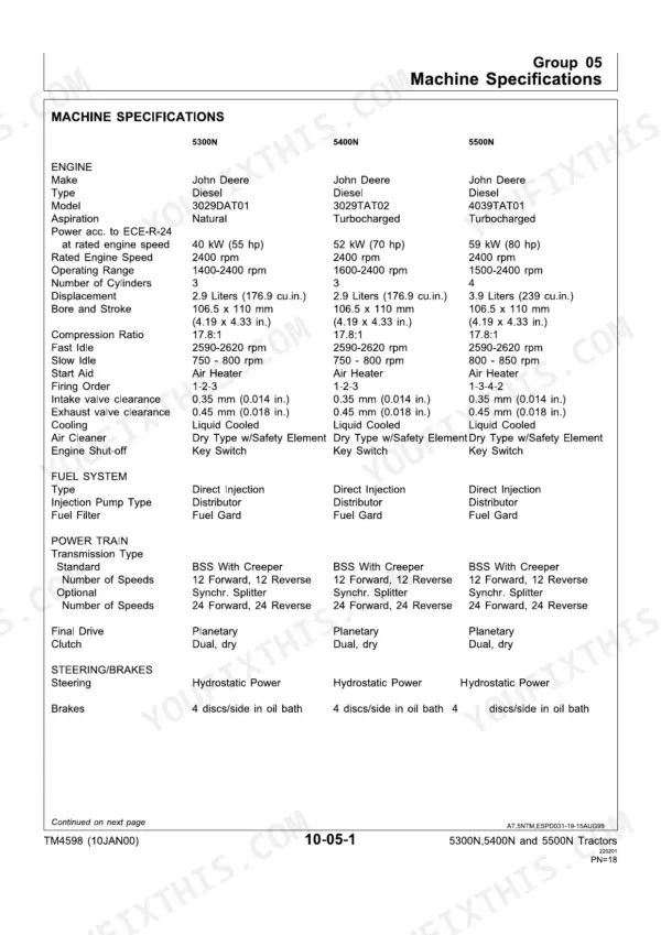
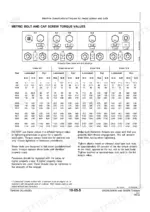
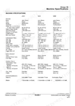
| General Specifications | 21-40 | Machine Specifications, Metric Cap Screw Torque Values, Diesel Fuel and Lubricants, Serial Number Plates |
| Repair - Engine | 41-54 | Remove and Install Engine, Remove and Inspect Radiator, Install Radiator, Engine Support and Lifting |
| Repair - Fuel and Air Intake Systems | 55-66 | Remove, Inspect and Install Fuel Tank, Speed Control Linkage, Air Cleaner Elements, Air Intake System |
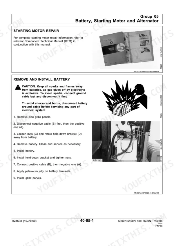
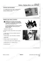
| Repair - Electrical System | 67-89 | Battery, Starting Motor and Alternator, Switches and Sensors, Instrument Panel and Transmission Wiring Harnesses |
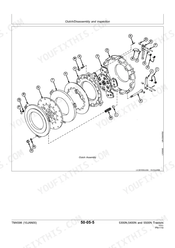
| Repair - Power Train | 90-248 | Clutch Housing and Clutch Pedal, Transmission (Range, Primary, Reverse, Pinion and Secondary Shafts), Power Take-Off (Controls, Drive Shaft, Shift Lever and Linkage), Differential (Bearing Pre-Load, Backlash, Differential Lock), Final Drives and Planetary Drive, Mechanical Front Wheel Drive and Differential Carrier |
| Repair - Steering and Brakes | 249-302 | Steering Valve and Cylinder, Steering Column, Service Brakes, Parking Brake Lever and Linkage, Trailer Brake Valve |
| Repair - Hydraulic System | 303-350 | Hydraulic Pump and Oil Filter, Hydraulic Lines, Rockshaft (Control Lever, Linkage and Control Valve), Draft Control, Selective Control Valve |
| Repair - Miscellaneous | 351-400 | Front Axle Without MFWD (Pivot Pin and Bushings), Front Wheel Bearings, Three-Point Hitch, Wheels and Tires, Operator Station |
| Operation and Tests - Electrical System | 401-566 | Component Location, Theory of Operation, Wiring Schematics, Diagnosis, Starting and Charging System Test Points, Tests and Adjustments |
| Operation and Tests - Power Train and Steering | 567-688 | Component Location, Theory of Operation (Incl. Steering Valve Operation), Diagnosis, Clutch and Transmission Tests, Steering Tests and Adjustments |
| Operation and Tests - Hydraulic System | 689-782 | Component Location, Theory of Operation, Diagnosis, Hydraulic Pressure and Flow Tests, Rockshaft and SCV Adjustments |
Quick Reference Specifications
| Specification | Value | Page |
|---|---|---|
| All Models | ||
| Hydraulic Pump Type | Tandem Gear | p. 24 |
| Hydraulic System Type | Open Center | p. 24 |
| Fuse 1 (R.h. low beam headlight) | 7.5 amp | p. 414 |
| Fuse 2 (L.h. low beam headlight) | 7.5 amp | p. 414 |
| Tractor moves smoothly going straight | Tractor moves smoothly going straight | p. 617 |
| 5300N | ||
| Engine Crankcase w/Filter | 6 L (6.3 U.S. qt) | p. 25 |
| Engine Power, 5300N | 40 kW (55 hp) | p. 23 |
| 5400N | ||
| Engine Power, 5400N | 52 kW (70 hp) | p. 23 |
John Deere 5300N, 5400N, 5500N Common Problems This Manual Covers
John Deere 5300N hydraulic pump loses pressure, rockshaft won't lift or lifts slowly under load
Check hydraulic oil level; the system holds 43 L (11.3 U.S. gal) with high-low transmission. Warm the oil to 38 to 43°C (100 to 110°F), the test temperature given on page 726, before judging pump output. Inspect the hydraulic filter, steering filter, and suction line for restriction, then test the relief valve before condemning the tandem gear pump.
Manual Section: Hydraulic System: Insufficient Pump Delivery p. 726Fuse for PTO switch and fuel shut-off solenoid keeps blowing, engine dies in the field
Check fuse 11 first; it feeds the PTO switch, fuel shut-off solenoid, instrument panel, and alternator, and the chart on page 414 rates it at 7.5 amps. Replace it, then wiggle-test the harness connectors while watching for the blow. Never install a bigger fuse; find the chafed wire or loose connection and repair it.
Manual Section: Electrical System p. 414Engine cranks slowly or starter clicks once, no start on cold mornings
Test battery voltage first; the battery is rated 100 Ah with 400 cold cranking amps, and a weak one masks every other fault. Work the starting system test points in order: starter terminal, key switch, fuse, fuel shut-off solenoid, and start relay, using the diagnostic test values beginning. Clean and tighten grounds before replacing the starter.
Manual Section: Electrical System: Starting System Test PointsTransmission jerky and rough, gears clash when shifting, tractor pops out of gear under load
Check transmission oil level before anything else; low oil is the top cause of jerky, rough operation. Drain and inspect for debris if gears clash, then follow the power train troubleshooting procedures starting. Torque any M10 Grade 7 case hardware you disturb to 47.5 to 54.2 N-m (35-40 lb-ft).
Manual Section: Power Train: Transmission TroubleshootingRemote cylinder settles under load, implement drifts down within minutes of parking
Verify oil temperature is 38 to 43°C (100 to 110°F) before any settling test; cold oil gives false readings. Check the remote cylinder for internal leakage past the piston seals, then inspect the control valve. Spools and housing are matched parts, so replace the valve as a unit per page 346, never the spool alone.
Manual Section: Hydraulic System: Remote Cylinder Troubleshooting p. 346Frequently Asked Questions
What is the engine oil capacity for the John Deere 5300N, 5400N, and 5500N tractors, including the filter?
For the 5300N, 5400N, and 5500N tractors, the engine crankcase capacity with the filter is 6 L (6.3 U.S. qt) for the 5300N and 8.5 L (9 U.S. qt) for the 5400N and 5500N models. p. 25
What is the cooling system capacity for the John Deere 5300N, 5400N, and 5500N tractors?
The cooling system capacity for the John Deere 5300N, 5400N, and 5500N tractors is approximately 9.5 L (10 U.S. qt). p. 25
What are the battery specifications for the John Deere 5300N, 5400N, and 5500N tractors?
The battery size for the John Deere 5300N, 5400N, and 5500N tractors is 100 Ah with 400 Cold Cranking Amps at -18°C (0°F). The electrical system type is 12 Volt. p. 24
What is the regulated voltage for the alternator on John Deere 5300N, 5400N, and 5500N tractors?
The regulated voltage for the alternator on John Deere 5300N, 5400N, and 5500N tractors is 14.2 to 14.8 V at 10 amps or less, when operating at 2400 rpm and 25°C (77°F). p. 24
What is the torque specification for the engine-to-clutch housing cap screw on John Deere 5300N, 5400N, and 5500N tractors?
The engine-to-clutch housing cap screw should be tightened to a torque of 240 N-m (178 lb-ft). This is a critical specification for engine installation. p. 44
How quickly can I access this John Deere 5300N manual after buying?
You get a 782-page searchable PDF that downloads instantly after checkout. Open it on your laptop, tablet, or phone, and bring it right to the shop floor.
Am I able to print pages from this manual?
Yes. Print the sections you need to take out to the shop for your own use. Standard letter or A4 paper works.