
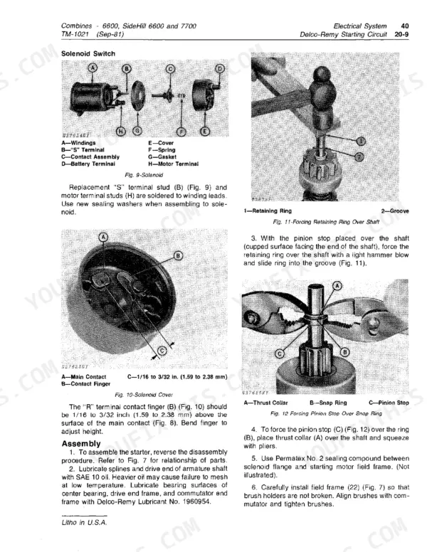
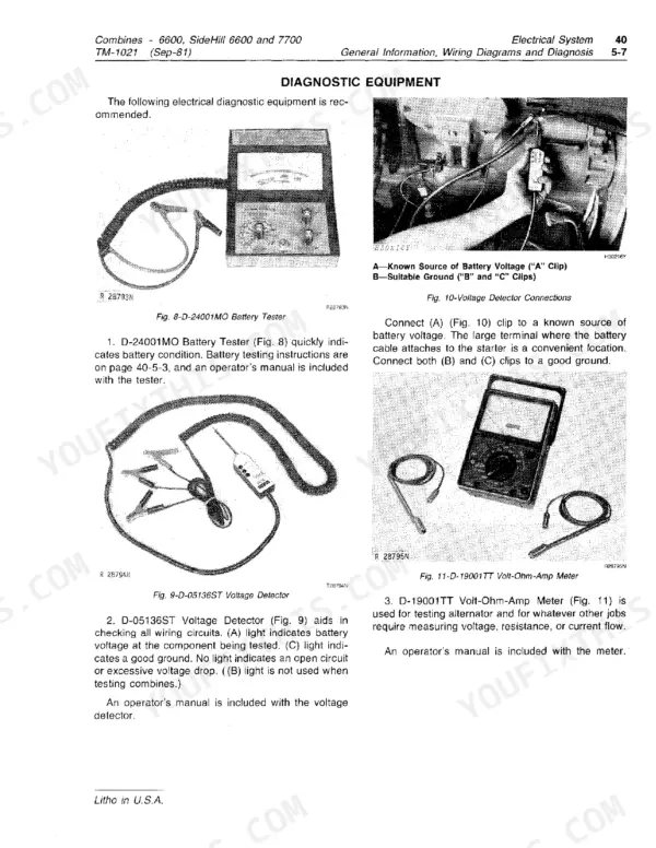
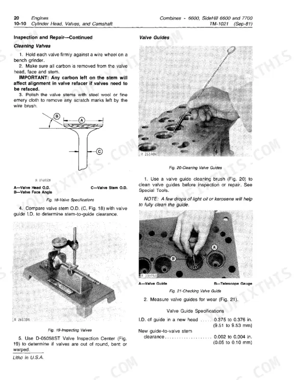
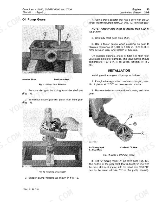
Part of the John Deere Repair Manuals.
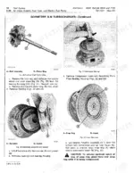
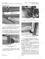
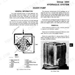
TM1021 is John Deere's technical manual for the 6600, SideHill 6600 and 7700 combines. Repair, diagnosis and specifications are all in this one book.
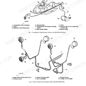
It covers the 303, 329, 362 and 404 engines, including the 404 Turbo, plus the Sundstrand hydrostatic drive, power steering, brakes and the SideHill leveling system. It includes the wiring diagrams, the hydraulic system diagram and step-by-step diagnosis charts.
The chapters run by system: headers, feeder house, separator, grain tank and augers, then major drives.
What's Inside This John Deere 6600, SideHill 6600, 7700 Manual
| System | Pages | Key Topics |
|---|---|---|
| General Specifications and Predelivery | 1-64 | Contents, Dimensions and Capacities, Engine and Transmission Summary, Controls and Instruments, Predelivery, Delivery and After-Sale Inspection |
| Lubrication, Diagnosis and Tune-Up | 65-94 | Oils and Viscosities, Lubrication Points, Diagnosing and Testing, Compression Test, Engine Oil Pressure, Valve Clearance, Ignition, Adjustments |
| Engines: Cylinder Head, Block and Crankshaft | 95-154 | Engines 303, 329, 362 and 404, Diagnosis, Removal, Cylinder Head, Valves, Camshaft, Liners, Pistons, Connecting Rods, Crankshaft, Flywheel |
| Engines: Lubrication, Cooling and Governor | 155-226 | Oil Pump and Filter, Radiator and Fan, Water Pump, Rotary Screen, Governor and Speed Control Linkage, Specifications, Special Tools |
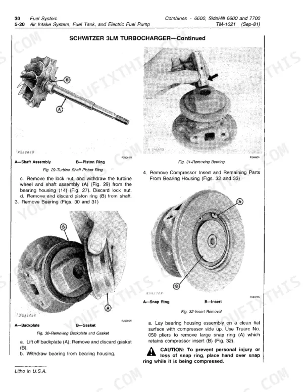
| Fuel System | 227-340 | Air Intake, Fuel Tank, Electric Fuel Pump, Diesel Injection Pump, Injection Nozzles, Filters, Carburetor, Gasoline Fuel Pump, Specifications |
| Electrical System: Wiring Diagrams and Diagnosis | 341-366 | Wiring Diagrams, Electrical Diagnosis, Main Harness, Cab Wiring, Low Shaft Speed Monitor Wiring |
| Charging, Starting and Ignition Circuits | 367-454 | Motorola and Delcotron Alternators, Voltage Regulator, Delco-Remy and John Deere Starters, Relays, Ignition Circuit, Distributor |
| Lights, Instruments and Shaft Speed Monitor | 455-534 | Lights, Instruments, Switches, Low Shaft Speed Monitor, Harness Replacement, Batteries, Fuses, Specifications |
| Power Train: Clutch, Transmission and Final Drives | 535-594 | Clutch, Master Cylinder, Transmission, Differential, Final Drives |
| Hydrostatic Drive, Rear Wheel Drive and Tracks | 595-752 | Sundstrand Hydrostatic Drive, Power Rear Wheel Drive, Posi-Torq Ground Drive, Tires and Wheels, Crawler Tracks |
| Power Train Specifications, Power Steering and Brakes | 753-816 | Power Train Specifications, Power Steering, Steering Pump, Brakes, Brake Fluid, Specifications |
| Hydraulic System Operation and Tests | 817-964 | Hydraulic System Diagram, Operation, Glossary, Diagnosing Malfunctions, Step-By-Step Diagnosis Charts |
| Hydraulic Components and Specifications | 965-1048 | Reservoir, Cessna Pumps, Control Valves, Cylinders, Motors, Oil Lines and Hoses, Relief Pressures, Capacities |
| Operator's Cab | 1049-1152 | Cab Pressurizer, Air Conditioning, Refrigerant, Heater, Personal Posture Seat, Miscellaneous, Specifications |
| Headers | 1153-1250 | 200 Series Platforms, Quik-Tatch Platforms, 40 Series Corn Heads, Row-Crop Heads, Specifications |
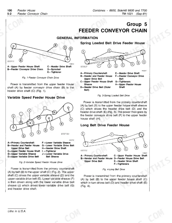
| Feeder House | 1251-1284 | Conveyor Chain and Drum, Paddles and Stripper, SideHill, Variable Speed Drive, Lower and Upper Shafts, Specifications |
| Separator | 1285-1384 | Cylinder, Concave and Beater, Cylinder Drives, Straw Walkers, Straw Chopper and Spreader, Shoe, Fan and Sieves, Tailings, Clean Grain Elevator, Specifications |
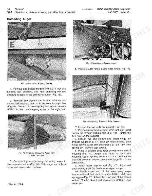
| Grain Tank and Unloading Augers | 1385-1404 | Auxiliary Augers, Inner and Outer Unloading Augers, Grain Tank, Specifications |
| Major Drives | 1405-1428 | Engine Powershaft, Primary and Secondary Countershaft, Separator Control Lever, Specifications |
| SideHill 6600 Leveling System | 1429-1490 | General Information, Electrical Components, Hydraulic Components, Leveling Cylinders |
| Header Height Control and Unloading Auger Swing | 1491-1550 | Automatic Header Height Control Diagnosis, Mechanical, Electrical and Hydraulic, Unloading Auger Swing and Latching, Specifications |
| Machine Reconditioning | 1551-1564 | Cleaning, Servicing and Repainting, Decal and Label Installation, Shields and Guards |
Quick Reference Specifications
| Specification | Value | Page |
|---|---|---|
| Engines | 6-cylinder gasoline 303, 329, 362; diesel 329, 404, 404 Turbo | p. 97 |
| Engine speed | Slow idle 800 rpm (gasoline), fast idle 2650 rpm | p. 8 |
| Valve clearance, gasoline 303 and 329 | Intake 0.014 in. (0.356 mm), exhaust 0.022 in. (0.559 mm) | p. 86 |
| Valve clearance, diesel 404 Turbo | Intake 0.018 in. (0.457 mm), exhaust 0.028 in. (0.711 mm) | p. 86 |
| Spark plug gap and torque | 0.025 in. (0.635 mm) gap, 35 ft-lbs (45 Nm) | p. 88 |
| Compression, 404 Turbo | 330-370 psi (22-25 bar) | p. 85 |
| Engine oil pressure, gasoline 329 | 45 to 65 psi (3.0 to 4.4 bar) at 2500 rpm | p. 88 |
| Cooling system, 303 and 329 | 28 U.S. Qts. (27 L) | p. 9 |
| Cooling system, 362 and 404 | 32 U.S. Qts. (30 L) | p. 9 |
| Fuel tank | 6600: 57 U.S. Gals. (216 L); 7700: 72 U.S. Gals. (273 L) | p. 9 |
| Transmission | 11 U.S. Qts. (10.5 L) | p. 9 |
| Hydraulic system capacity | 6600 and 7700: 17-1/2 U.S. Qts. (16.55 L); SideHill 6600: 24-1/2 U.S. Qts. (23 L) | p. 1044 |
| Hydraulic reservoir | 14 U.S. Qts. (13.3 L) | p. 1044 |
| Main system relief pressure | 2000 psi (136 bar) early machines, 2250 psi (153 bar) later and SideHill 6600 (+ 100 psi) | p. 1043 |
| Steering system relief pressure | 1250 psi (85 bar) to 1750 psi (119 bar) by serial number | p. 1043 |
| Hydrostatic drive high-pressure relief | 5300 psi (360 bar) + 200 psi (14 bar) | p. 754 |
| Hydrostatic charge relief (nominal) | 180 psi (12 bar) | p. 754 |
| Separator speeds | Straw walkers 157 rpm, straw chopper 2358 rpm, cleaning fan 272-965 rpm | p. 1381 |
| Lock nut on powershaft | 240 ft-lbs (325 N-m) | p. 1382 |
| Grain tank without extensions | 6600 and SideHill 6600: 112 bu. (3.95 m3); 7700: 129 bu. (4.55 m3) | p. 1403 |
John Deere 6600, SideHill 6600, 7700 Common Problems This Manual Covers
Pump output low
Work through the step-by-step diagnosis chart in the hydraulic operation and tests section. Check oil supply in the 14 U.S. Qt. reservoir first. Then check for a loose drive belt (reel drive only), a restricted suction line or filter, and correct engine speed. If those check out, look for dirt in the pump or internal wear and leakage. The Cessna pump procedures are in the hydraulic components section.
Manual Section: Hydraulic System Tests - Diagnosing Malfunctions p. 867Hard steering
Start by checking for oil leaks or damaged lines and for low pump pressure. Steering relief should be 1250 psi to 1750 psi depending on serial number. The power steering section then covers a sticking relief valve or spool and an incorrectly assembled steering valve. It also covers internal cylinder leakage, a worn pump or flow divider, and a plugged orifice in the flow divider valve.
Manual Section: Hydraulic System Tests - Diagnosing Malfunctions p. 867Selective ground speed cylinder or header lift cylinders will not operate or are slow to operate
Check oil level, then tee in a gauge. Main relief should be 2000 psi on early machines and 2250 psi on later ones and the SideHill 6600. The diagnosis charts also cover restricted spool travel, a sticking lock-out plunger, plugged orifices and leaking O-rings. They also cover sludge in the system, a worn pump and pressure lock in the header lift cylinder lines.
Manual Section: Hydraulic System Tests - Diagnosing Malfunctions p. 867Overheated engine
Check that the rotary screen turns and is clean, then check for a plugged radiator. Check coolant level: 28 U.S. Qts. on the 303 and 329, or 32 U.S. Qts. on the 362 and 404. The cooling section then covers a loose fan belt, the thermostat, the water pump and a leaking head gasket.
Manual Section: Engines - Diagnosing Malfunctions p. 99Frequently Asked Questions
Which engines are in the John Deere 6600, SideHill 6600 and 7700 combines?
All of them are John Deere 6-cylinder, valve-in-head, liquid-cooled engines. The 6600 got gasoline 303 and 329 engines or diesel 329 and 404 engines. The SideHill 6600 is diesel 404 only, including the 404 Turbo. The 7700 ran a gasoline 362 or a diesel 404, turbo version included. Valve clearance is listed for each engine. On the gasoline 303 and 329 it is 0.014 in. (0.356 mm) intake and 0.022 in. (0.559 mm) exhaust. p. 97
What are the cooling system, fuel tank and hydraulic capacities on the 6600 and 7700?
The cooling system holds 28 U.S. Qts. (27 L) on the 303 and 329 and 32 U.S. Qts. (30 L) on the 362 and 404. The fuel tank is 57 U.S. Gals. (216 L) on the 6600 and 72 U.S. Gals. (273 L) on the 7700. The complete hydraulic system takes 17-1/2 U.S. Qts. (16.55 L) on the 6600 and 7700. The SideHill 6600 takes 24-1/2 U.S. Qts. (23 L). The reservoir alone holds 14 U.S. Qts. (13.3 L). p. 9
What are the hydraulic relief pressures on the 6600, SideHill 6600 and 7700?
Main system relief is 2000 psi (136 bar) on the 6600 (-156500) and the 7700 (-163900). Later machines and the SideHill 6600 run 2250 psi (153 bar). Both settings allow plus or minus 100 psi. Steering relief depends on serial number, from 1250 psi (85 bar) on early 6600s up to 1750 psi (119 bar) on later machines. Hydrostatic drive high-pressure relief is 5300 psi (360 bar), plus or minus 200 psi (14 bar). Charge relief is 180 psi (12 bar) nominal. p. 1043
What are the separator speeds on the 6600 and 7700?
Straw walkers run at 157 rpm and the straw chopper at 2358 rpm. The cleaning fan runs at 272-965 rpm. Torque the lock nut to 240 ft-lbs (325 N-m). p. 1381
Which oils go in the transmission, final drives and hydrostatic drive?
The transmission takes John Deere Hy-GARD Transmission and Hydraulic Oil or an equivalent, 11 U.S. Qts. (10.5 L). Final drives and gear cases take John Deere SAE HD 90-140 Gear Lubricant. The hydrostatic drive reservoir takes John Deere All-Weather Hydrostatic Fluid or Texaco Type F Automotive Automatic Transmission Fluid. p. 66








Reviews
There are no reviews yet.