
Part of the John Deere Repair Manuals.
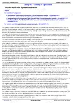
This is the Operation and Test manual (TM11743) for the John Deere 744K 4WD loader, serial numbers 632968-664100. It is the diagnostics book, not the teardown book: fault code trees in SPN.FMI format (a restricted engine air filter reads 000107.00), theory of operation, and test procedures for the ECU, TCU, VCU, SSM, ADU, ROD, RDR, JSV, JSC, and TPM controllers. You also get the full electrical schematic with W1-W42 harness wiring diagrams, the operational checkout, turbo boost testing on the 6090HDW08, hydraulic circuit diagnostics from steering to ride control, power train tests and adjustments, and R134a charge and pressure specs. Torque values and disassembly live in the companion Repair TM - this book finds the problem first.
What's Inside This John Deere 744K Manual
| System | Pages | Key Topics |
|---|---|---|
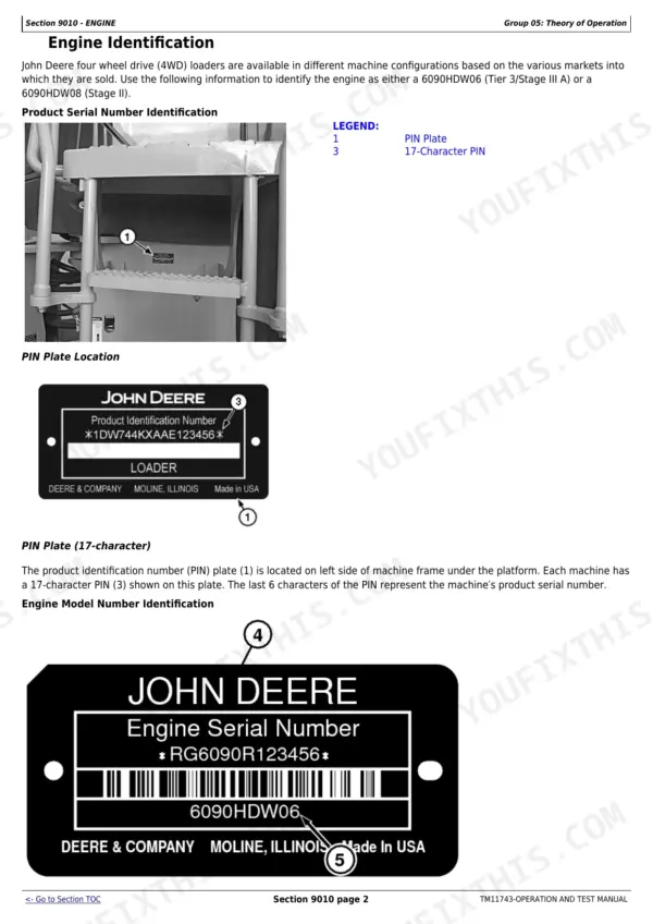
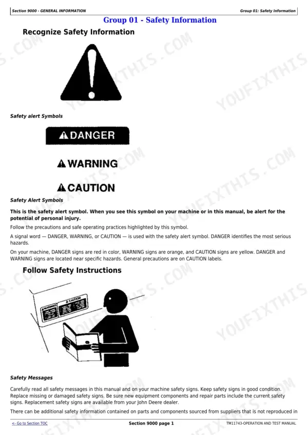
| General Information | 8-36 | Safety Information, Manual Identification, Serial Number and Pin Identification |
| Diagnostic Trouble Codes - Engine and Transmission | 37-202 | Group 10 Engine Control Unit (ECU) Codes, Group 20 Transmission Control Unit (Tcu) Codes |
| Diagnostic Trouble Codes - Vehicle Control Unit | 203-511 | Group 30 Vehicle Control Unit (Vcu) Codes |
| Diagnostic Trouble Codes - Switch Module and Display | 512-612 | Group 40 Sealed Switch Module (Ssm) Codes, Group 50 Advanced Display Unit (Adu) Codes |
| Diagnostic Trouble Codes - Radar, Joystick Steering and Tire Pressure | 613-649 | Group 60 Radar Object Detection (Rod), Group 70 Ground Speed Radar (Rdr), Group 80 Joystick Steering Valve (Jsv), Group 90 Joystick Steering Controller (Jsc), Group 100 Tire Pressure Monitoring (Tpm) |
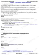
| Operational Checkout Procedure | 650-683 | Operational Checkout |
| Engine | 684-721 | Theory of Operation, Fast Fill Fuel System, Fluid Sampling Procedure, Turbocharger Boost Test, Engine Idle Speeds, Auto Idle/Shutdown |
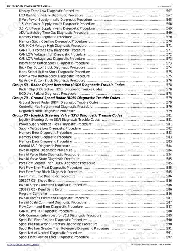
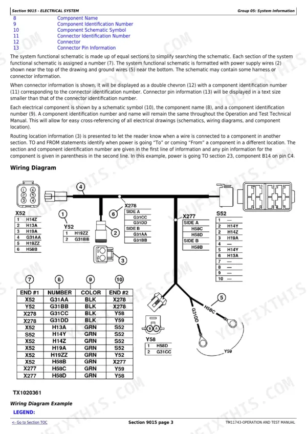
| Electrical System | 722-1061 | System Functional Schematic, Component Wiring Diagrams (Harnesses W1-W42), Sub-System Diagnostics, Monitor Operation |
| Power Train | 1062-1226 | Theory of Operation, Diagnostic Information, Adjustments, Tests |
| Hydraulic System | 1227-1491 | Hydraulic System Schematic, Steering and Orbital Valve, Loader Control Valve, Service Brakes, Ride Control, Diagnostic Procedures |
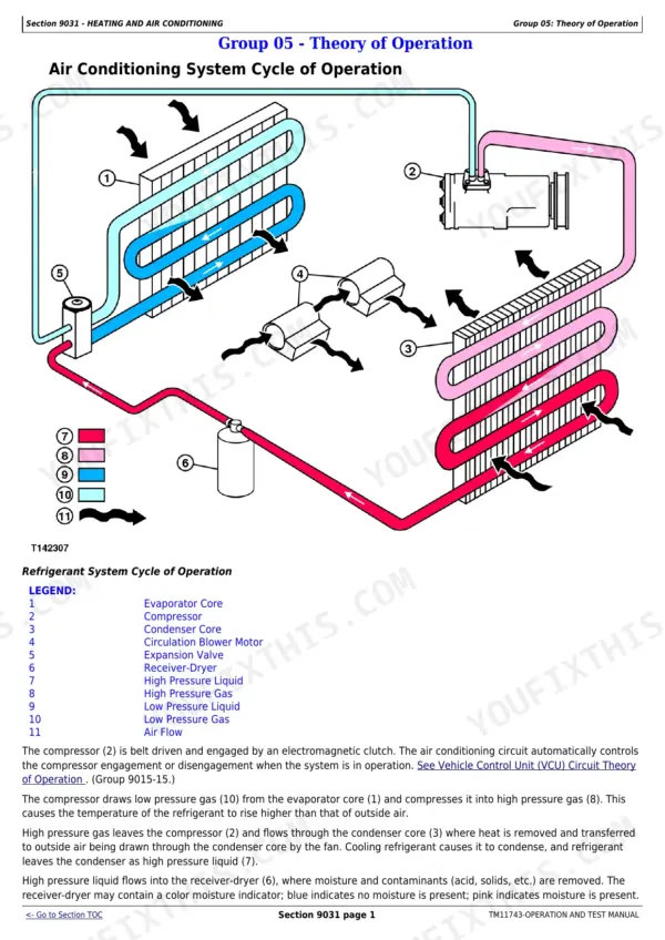
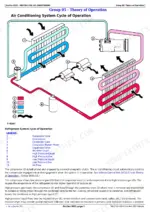
| Heating and Air Conditioning | 1492-1516 | Theory of Operation, Blower Speed Switch Tests, R134a Charge and Pressure Tests |
Quick Reference Specifications
| Specification | Value | Page |
|---|---|---|
| Engine Slow Idle Speed | 900 rpm | p. 717 |
| Engine Fast Idle Speed | 2000 rpm | p. 717 |
| Turbocharger Boost Pressure (6090HDW08 @ 2180 rpm) | 144.79-165.47 kPa (21-24 psi) | p. 716 |
| Auto idle/shutdown coolant temperature threshold | less than 90 C (194 F) | p. 717 |
| Engine oil sampling interval | 250 hours | p. 712 |
| Coolant/hydraulic/transmission oil sampling interval | 500 hours | p. 712 |
| Hydraulic Oil Temperature (normal) | 60-70 C (140-160 F) | p. 1457 |
| Service Brake Accumulator Gas Precharge Pressure | 1070-1207 kPa (155-175 psi) | p. 1457 |
| Service Brakes Applied Pressure | 1944-3447 kPa (282-500 psi) | p. 1460 |
| Pin Disconnect Pressure | 6033-6378 kPa (875-925 psi) | p. 1467 |
| Pump Cut-Off Pressure | 23100-23800 kPa (3350-3450 psi) | p. 1471 |
| New Hydraulic Fan Pump Flow Rate (minimum) | 51 L/min. (13.5 gpm) | p. 1480 |
| R134a Refrigerant Charge Capacity | 2.72 kg (6.00 lb.) | p. 1509 |
| AC System Low-Side Pressure (ambient 19-21 C) | 84-102 kPa (12-15 psi) | p. 1512 |
| AC System High-Side Pressure (ambient 19-21 C) | 923-1118 kPa (134-162 psi) | p. 1512 |
John Deere 744K Common Problems This Manual Covers
Intermittent fault code from the transmission or vehicle controller that clears before anyone can look at it
Write down the exact SPN.FMI number from the display, then work the matching TCU or VCU code tree in the Diagnostic Trouble Codes section. Each tree steps through connector, harness, and sensor checks so an intermittent gets isolated to a circuit, not a guess.
Manual Section: Diagnostic Trouble Codes (DTC) p. 37Brake pedal feels spongy or the machine loses brake assist after a few applications with the engine off
That points at the service brake accumulators. The Hydraulic System section gives the gas precharge test procedure and the spec, 1070-1207 kPa (155-175 psi). Test each accumulator against that number before condemning the brake valve or pump.
Manual Section: Hydraulic System - Service Brakes p. 1457Engine feels down on power under load but throws no active codes
Run the turbocharger boost test in the Engine section. On the 6090HDW08, at the test's specified fast-idle speed of 2180 rpm you should see 144.79-165.47 kPa (21-24 psi) of boost. Low readings send you toward air filter restriction, charge air leaks, or the turbo itself.
Manual Section: Engine - Turbocharger Boost Test p. 716AC blows warm in summer heat and nobody knows if the system is undercharged or the compressor is failing
Use the R134a system charge and pressure tests. Compare gauge readings to the ambient temperature tables - low side of 84-102 kPa (12-15 psi) at 19-21 C - and verify the full 2.72 kg (6.00 lb) charge before replacing hardware.
Manual Section: Heating and Air Conditioning p. 1509Frequently Asked Questions
Does this manual cover my 744K serial number?
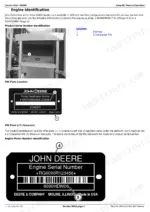
It covers serial numbers 632968 through 664100, the earlier 744K build. Machines after SN 664100 are the later Series II and use a different manual. Check the PIN plate before you buy - the General Information section shows exactly where to find it. p. 5
Will this help me chase a fault code the dash keeps throwing?
Yes, that is the core of the book. Codes are listed in SPN.FMI format - 000107.00 is a restricted engine air filter, for example - with diagnostic trees for ten controllers: ECU, TCU, VCU, SSM, ADU, ROD, RDR, JSV, JSC, and TPM. You follow the tree for your code instead of guessing at sensors. p. 38
Does it include torque specs and teardown procedures?
No, and I will not pretend it does. This is the Operation and Test manual: diagnostics, theory of operation, pressure tests, and adjustments. Component disassembly and torque tables are in the companion Repair TM. If you are splitting a pump or pulling the transmission, you need both books.
Are the wiring diagrams actually usable for harness troubleshooting?
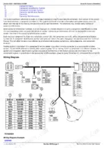
The Electrical System section has the full system functional schematic plus individual wiring diagrams for harnesses W1 through W42, along with sub-system diagnostics. You can trace a circuit from the controller pin to the component instead of ringing out wires blind. p. 741
Can I service the air conditioning with this manual?
For diagnostics and charging, yes. It gives the R134a charge capacity of 2.72 kg (6.00 lb) and pressure test tables - low side should read 84-102 kPa (12-15 psi) at 19-21 C ambient - plus blower speed switch checks. Compressor teardown is Repair TM territory. p. 1509








Reviews
There are no reviews yet.