
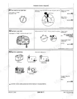
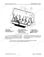
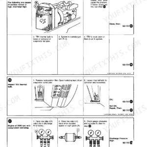
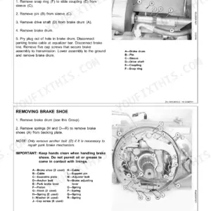
Part of the John Deere Repair Manuals.
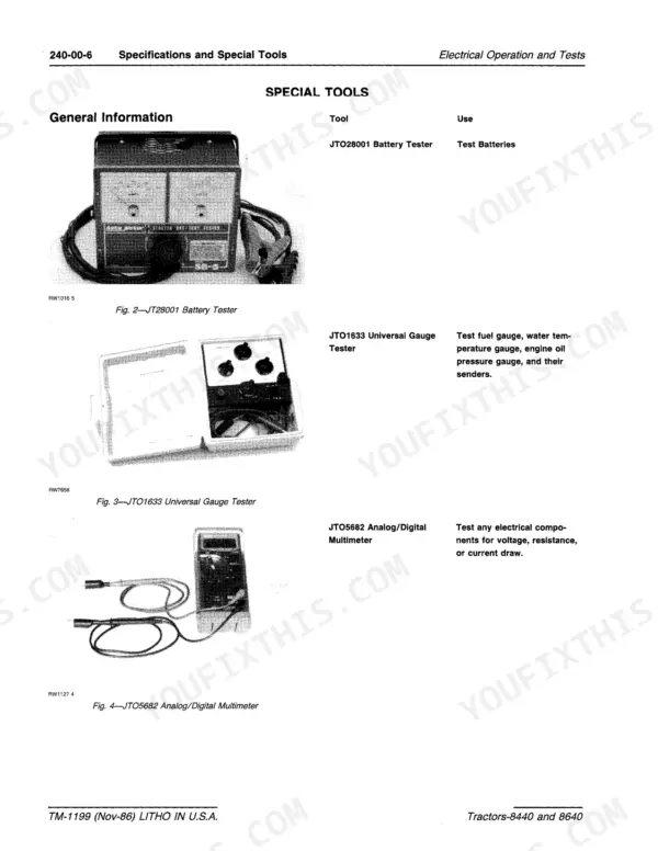
TM-1199 covers the John Deere 8440 and 8640 four-wheel-drive tractors. The Repair sections and the Operation and Tests sections are in one volume.
This book gives the factory figures, from the 8640 cylinder head cap screw torque to the rockshaft surge relief opening pressure. It also has the tractor wiring diagram and the hydraulic circuit diagrams.
Repair runs from Section 10 to Section 95, and Operation and Tests from 220 to 290.
What's Inside This John Deere 8440, 8640 Manual
| System | Pages | Key Topics |
|---|---|---|
| General, Predelivery, Tune-Up, Lubrication and Separation | 1-98 | Specifications, Special Tools, Predelivery, Tune-Up, Lubrication, Separation |
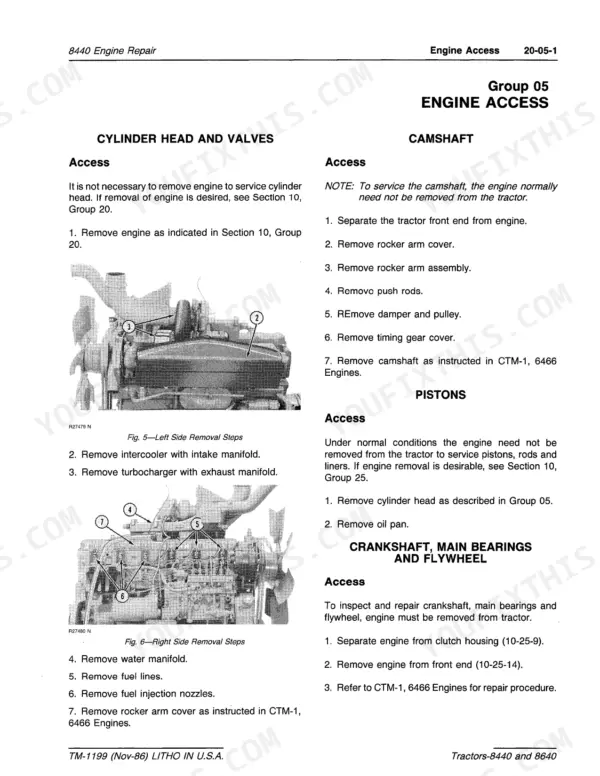
| 8440 Engine Repair (Access and Cooling) | 99-106 | Engine Access, Cooling System, Radiator, Water Pump |
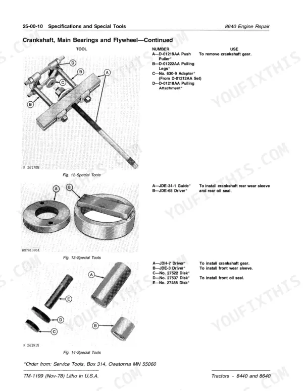
| 8640 Engine Repair | 107-176 | Cylinder Head, Valves, Camshaft, Pistons, Liners, Crankshaft, Lubrication, Cooling |
| Fuel and Air Systems Repair | 177-234 | Air Cleaner, Turbocharger, Intercooler, Fuel Tank, Injection Pump, Nozzles, Speed Control |
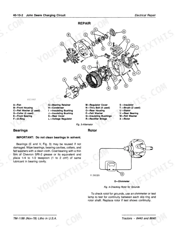
| Electrical Repair | 235-272 | Batteries, Harness, Alternator, Starter, Lighting, Instrument, Warning, Accessory Circuits |
| Power Train Repair | 273-446 | Perma-Clutch, Quad-Range, PTO, Torque Divider, Differentials, Final Drives |
| Steering and Brakes Repair | 447-476 | Power Steering, Steering Valve, Cylinders, Power Brakes, Brake Valve |
| Hydraulic System Repair | 477-554 | Hydraulic Pumps, Rockshaft, Hitch, Selective Control Valve, Breakaway Coupler, Remote Cylinder |
| Wheels and Operator Station Repair | 555-614 | Wheels, Air Conditioning, Compressor, Heater, Seat, Sound-Gard Body |
| Miscellaneous Options | 615-650 | Auxiliary Lighting, Auxiliary Steering, Auxiliary Brake, Trailer Brakes |
| Engine Operation and Tests | 651-670 | Cooling System Operation, Lubrication, Dynamometer Test, Break-In, Malfunctions |
| Fuel and Air Operation and Tests | 671-706 | Air Intake, Turbocharger, Fuel Flow, Injection Pump Timing, Nozzle Tests, Diagnosis |
| Electrical Specifications and Wiring Diagrams | 707-720 | Batteries, Circuit Breakers, Tractor Wiring, Schematic Diagram, Electrical Components |
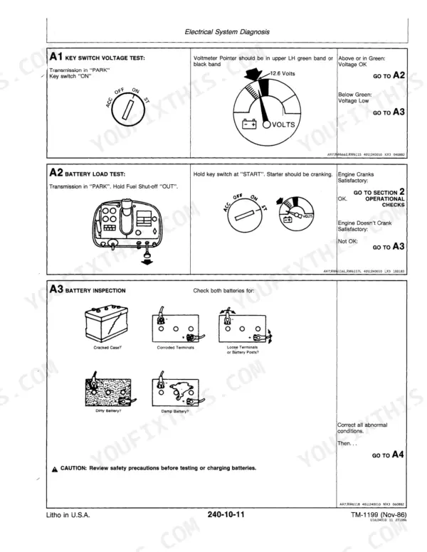
| Electrical System Diagnosis | 721-836 | Step-By-Step Diagnosis, Quick Check |
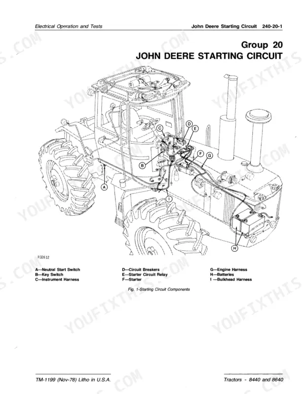
| Charging, Starting, Lighting, Instrument and Accessory Circuits | 837-884 | Alternator, Starting Circuit, Lighting, Warning System, Accessory, Remote Control, Outlet Socket |
| Power Train Operation and Tests | 885-942 | Quad-Range, Power Flow, PTO, Torque Divider, Differential, Lube Pressure, Diagnosis |
| Steering and Brakes Operation and Tests | 943-958 | Power Steering, Pressure Circuit, Return Circuit, Power Brakes, Accumulator, Diagnosing Malfunctions |
| Hydraulic System Operation | 959-982 | Specifications, Charge Circuit, High Pressure Circuit, Lubrication, Return Circuits, Valves |
| Hydraulic Tests and Diagnosis | 983-1012 | Step-By-Step Hydraulic Diagnosis, Pressure Tests |
| Hydraulic Components, Pumps, Rockshaft and SCV Operation and Tests | 1013-1076 | Filters, Oil Cooler, Main Pump, Rockshaft, Selective Control Valve, Remote Cylinder |
| Operator Station Operation and Tests | 1077-1124 | Air Conditioning, Electrical Testing, Diagnosis, Heater, Seat Suspension |
Quick Reference Specifications
| Specification | Value | Page |
|---|---|---|
| PTO horsepower at 2100 rpm (8440 / 8640) | 175 hp (130 kW) / 225 hp (168 kW) | p. 5 |
| Bore and stroke (8440 / 8640) | 4.56 x 4.75 in. (116 x 121 mm) / 5.12 x 5.00 in. (130 x 127 mm) | p. 5 |
| Displacement (8440 / 8640) | 466 cu. in. (7640 cm³) / 619 cu. in. (10 143 cm³) | p. 5 |
| Compression ratio (8440 / 8640) | 15.5 to 1 / 14.7 to 1 | p. 5 |
| Firing order | 1-5-3-6-2-4 | p. 5 |
| Valve clearance, intake (8440 / 8640) | 0.018 in. (0.46 mm) / 0.015 in. (0.38 mm) | p. 5 |
| Valve clearance, exhaust (8440 / 8640) | 0.028 in. (0.71 mm) / 0.025 in. (0.64 mm) | p. 5 |
| Slow idle speed | 780 to 820 rpm | p. 5 |
| Working speed range | 1500 to 2100 rpm | p. 5 |
| Fuel tank (8440 / 8640) | 156 U.S. gallons (590 L) / 200 U.S. gallons (757 L) | p. 6 |
| Cooling system (8440 / 8640) | 40 U.S. quarts (42 L) / 48 U.S. quarts (51 L) | p. 6 |
| Transmission-hydraulic system, wet (8440 / 8640) | 35 U.S. gallons (132 L) / 36 U.S. gallons (136 L) | p. 6 |
| PTO speed | 1000 rpm at 2100 engine rpm | p. 6 |
| Main hydraulic pump flow (4 cu. in. pump) | 28.5 gpm (108 L/m) @ 2000 rpm and 150°F (66°C) | p. 960 |
| Oil pressure regulating valve | 170 to 180 psi (11.7 to 12.4 bar) | p. 960 |
| Rockshaft surge relief valve opening pressure | 2650 to 3000 psi (182.7 to 206.8 bar) | p. 961 |
| Thermal relief valve opening pressure | 3550 to 3950 psi (244.8 to 272.4 bar) | p. 961 |
| 8640 cylinder head cap screws, second stage | 175 to 185 ft-lbs (237 to 251 N-m) | p. 109 |
| 8640 engine oil pressure | 40 to 55 psi (2.75 to 3.79 bar) | p. 110 |
| Alternator regulated voltage at 80°F (27°C) | 13.8 - 14.5 volts | p. 709 |
John Deere 8440, 8640 Common Problems This Manual Covers
Fuel not reaching the injection nozzles, or the engine starts hard or won't start
The fuel system diagnosing malfunctions chart lists a clogged fuel filter as a cause of fuel not reaching the nozzles. The remedy is to replace the filter. For a hard start or no start, check for water in the fuel. Drain the water and install new filters.
Manual Section: Fuel and Air Operation and Tests p. 686Low lubrication pressure in the power train
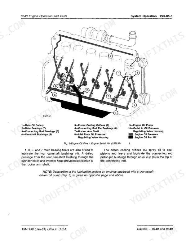
Check the transmission oil level first and top it up if it's low. If the level is good, the chart points to a stuck oil cooler relief valve, which is repaired per Section 70. Leaking adapter tube O-rings are the third cause. Remove the pressure regulating valve to replace them.
Manual Section: Power Train Operation and Tests p. 932SCV remote cylinder won't extend or moves too slowly
Make sure the SCV metering valve isn't set to the low flow position, and adjust it if it is. Then check for low transmission oil and top it up. Replace a plugged oil filter. If none of that fixes it, suspect the main pump and go to Section 70, Group 10.
Manual Section: Hydraulic Components, Pumps, Rockshaft and SCV Operation and Tests p. 1072Poor or no power brakes, or brakes won't release
Poor or no brakes can come from a failed brake piston packing or from water in the oil. If you find water, flush the system with oil and refill it. If the brakes won't release, the chart says to check whether the operating guides are stuck down.
Manual Section: Steering and Brakes Operation and Tests p. 958Frequently Asked Questions
Which tractors does TM-1199 cover, and does it include the Operation and Tests sections?
It covers the John Deere 8440 and 8640. The cover reads 8440 & 8640 Tractors (Repairs), but Operation and Tests (Sections 220 to 290) follow the Repair sections (10 to 95) in the same book. The 8440 uses the 6466A engine and the 8640 uses the 6619A. For a full 6466 engine repair the book sends you to component technical manual CTM-1. The 8640 engine repair section is complete. p. 4
What are the 8440 and 8640 engine specifications?
Both are six-cylinder in-line turbocharged, intercooled diesels. Factory observed PTO horsepower at 2100 rpm is 175 hp (130 kW) for the 8440 and 225 hp (168 kW) for the 8640. Bore and stroke are 4.56 x 4.75 in. (116 x 121 mm) and 5.12 x 5.00 in. (130 x 127 mm). Displacement is 466 cu. in. (7640 cm³) and 619 cu. in. (10 143 cm³). Compression ratio is 15.5 to 1 and 14.7 to 1. Firing order is 1-5-3-6-2-4. Slow idle is 780 to 820 rpm, and the working speed range is 1500 to 2100 rpm. p. 5
What are the 8440 and 8640 fluid capacities?
The fuel tank holds 156 U.S. gallons (590 L) on the 8440 and 200 U.S. gallons (757 L) on the 8640. The cooling system takes 40 U.S. quarts (42 L) and 48 U.S. quarts (51 L). The transmission-hydraulic system (wet) holds 35 U.S. gallons (132 L) and 36 U.S. gallons (136 L). PTO speed is 1000 rpm at 2100 engine rpm. p. 6
What hydraulic system pressures and flows does the manual give?
The main hydraulic pump (4 cu. in., 66 mL) delivers 28.5 gpm (108 L/m) at 2000 rpm and 150°F (66°C). The oil pressure regulating valve is set at 170 to 180 psi (11.7 to 12.4 bar). The rockshaft surge relief valve opens at 2650 to 3000 psi (182.7 to 206.8 bar). The thermal relief valve opens at 3550 to 3950 psi (244.8 to 272.4 bar). p. 960
Does the manual include wiring diagrams and hydraulic schematics?
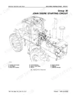
Yes. The electrical operation and tests section has the 8440-8640 tractor wiring diagram, a schematic of the electrical system and an electrical components locator. It also has alternator and starting circuit schematics. The hydraulic operation section has the overall hydraulic system schematic, the high pressure circuit and the transmission control and charge circuit diagrams. p. 718







Reviews
There are no reviews yet.