Part of the John Deere Repair Manuals.
An hour from now you could have the shroud off your F710 or F725 and this John Deere F710, F725 Technical Manual PDF open to the right procedure: all 648 pages of factory service data, published as TM1493 for both front mowers, the F710 paired with a 48-inch deck and the F725 with a 54-inch deck (p.41), the only two decks this manual covers. Wiring diagrams and hydraulic schematics back up separate tests-and-adjustments chapters for the FC540V and FD590V engines, so diagnosis on either machine starts at a component location drawing and ends at a measured pass-fail value. Repair chapters walk the hydrostatic transmission, steering, brakes, PTO assembly, and mower deck from removal through installation. Set the electric PTO clutch air gap between 0.38 and 0.64 mm. Guess wrong on that clutch and you buy it twice. Confirm at least 12.4 volts at the battery before you condemn a slow starter. Bookmarked and text searchable, this PDF is yours to keep once downloaded, for as long as the mower lives in your shed.
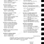
What's Inside This Manual
| System | Pages | Key Topics |
|---|---|---|
| General Information | 9-50 | Safety, General Specifications, Repair Specifications, Fuels and Lubricants, Serial Number Locations, Features and Attachments |
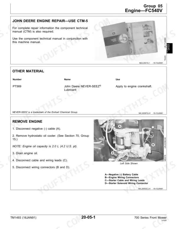
| Engine Repair F710 | 51-58 | Engine, Muffler, Engine Removal, Engine Installation |
| Engine Repair F725 | 59-74 | Engine, Muffler, Cooling System, Coolant Pump, Radiator, Thermostat |
| Fuel and Air Repair F710 | 75-86 | Carburetor, Fuel Pump, Fuel Filter, Fuel Tank, Air Cleaner, Blower Housing |
| Fuel and Air Repair F725 | 87-100 | Carburetor, Fuel Pump, Fuel Filter, Fuel Tank, Air Cleaner, Cooling Air Duct |
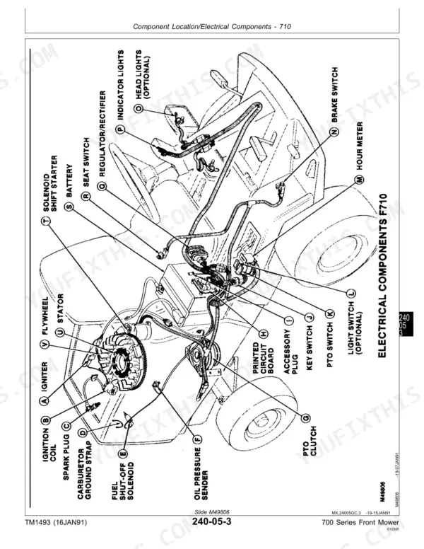
| Electrical Repair | 101-124 | Battery and Cables, Electrical System Components, Electric PTO Clutch, Wiring Harness |
| Power Train Repair | 125-162 | Hydrostatic Transmission and Differential Assembly, Hydrostatic Transmission, Differential Assembly |
| Steering and Brake Repair | 163-182 | Steering System Repair, Brake Repair |
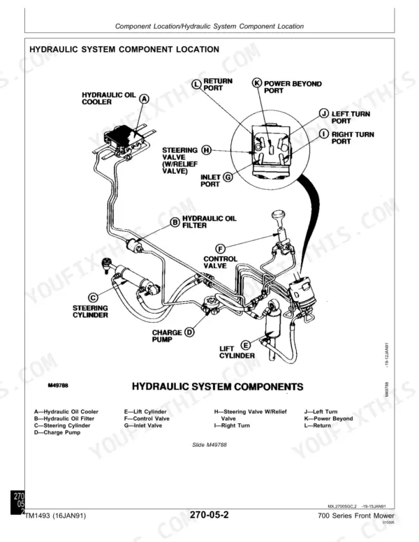
| Hydraulic Repair | 183-196 | Hydraulic Control Valve, Hydraulic Lift Cylinder, Hydrostatic Oil Cooler and Filter, Hydraulic Lines |
| Miscellaneous Repair | 197-234 | PTO Assembly, Rear Axle, Wheels and Bearings, Mower Deck Repair |
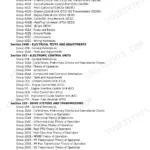
| Test and Adjustment Specifications/Operational Checkout Procedure | 235-254 | Test and Adjustment Specifications, Operational Checkout Procedures |
| Engine Operation, Tests and Adjustments FC540V Engine | 255-304 | FC540V Engine Component Location, Theory of Operation, Diagnosis, Tests and Adjustments |
| Engine Operation, Tests and Adjustments FD590V Engine | 305-354 | FD590V Engine Component Location, Theory of Operation, Diagnosis, Tests and Adjustments |
| Fuel/Air Operation Tests and Adjustments FC540V Engine | 355-372 | FC540V Engine Fuel/Air Component Location, Theory of Operation |
| Fuel/Air Operation Tests and Adjustments FD590V Engine | 373-390 | FD590V Engine Fuel/Air Component Location, Theory of Operation |
| Electrical Operation Tests and Adjustments FC540V Engine | 391-454 | FC540V Engine Electrical Component Location, Theory of Operation, Diagnosis, Tests and Adjustments, Wiring Schematics (p.453) |
| Electrical Operation Tests and Adjustments FD590V Engine | 455-520 | FD590V Engine Electrical Component Location, Theory of Operation, Diagnosis, Tests and Adjustments, Wiring Schematics (p.520) |
| Power Train Operation Tests and Adjustments | 521-556 | Hydrostatic Transmission and Differential Component Location, Theory of Operation, Diagnosis, Tests and Adjustments |
| Steering and Brakes Operation Tests and Adjustments | 557-584 | Steering System and Brakes Component Location, Theory of Operation, Diagnosis, Tests and Adjustments |
| Hydraulic Operation Tests and Adjustments | 585-618 | Hydraulic Control Valve and Lift Cylinder Component Location, Theory of Operation, Diagnosis, Tests and Adjustments |
| Miscellaneous Operation Tests and Adjustments | 619-640 | PTO, Rear Axle and Mower Deck Component Location, Theory of Operation, Diagnosis, Tests and Adjustments |
Quick Reference Specifications
| Specification | Value | Page |
|---|---|---|
| F710 | ||
| Engine Horsepower | 12.6 kW (17 hp) | p. 21 |
| Engine Oil Capacity | 1.9 L (4.0 U.S. pt) | p. 22 |
| Minimum Gap (Flywheel Screen) | 1.5 mm (0.059 in.) | p. 86 |
| Spark Plug Gap (FC540V Engine) | 0.7 to 0.8 mm (0.028 to 0.032 in.) | p. 238 |
| F725 | ||
| Engine Horsepower | 15 kW (20 hp) | p. 21 |
| Engine Oil Capacity | 2.1 L (4.44 U.S. pt) | p. 22 |
| Engine Coolant Capacity | 3.1 L (3.3 U.S. qt) | p. 22 |
| Spark Plug Gap (FD590V Engine) | 1.0 to 1.1 mm (0.039 to 0.043 in.) | p. 238 |
| All Models | ||
| Fuel Tank Capacity | 26.5 L (7.0 U.S. gal) | p. 22 |
| Engine-to-Frame Cap Screw Torque | 41 N·m (30 lb-ft) | p. 23 |
| PTO Clutch-to-Engine Cap Screw Torque | 67 N·m (50 lb-ft) | p. 23 |
| Fast Idle Setting | 3450 ± 100 rpm | p. 25 |
| System Relief Pressure | minimum 3620 kPa (525 psi) | p. 238 |
| PTO Clutch Amperage | 3.6 to 4.4 Amps | p. 436, 499 |
| PTO Clutch Resistance | 2.4 to 2.7 Ohm | p. 436, 499 |
| Starter Draw | maximum 85 amps @ minimum 500 rpm | p. 446, 511 |
| Starter No Load Draw | maximum 60 amps DC | p. 447, 512 |
| Minimum Battery Voltage | 12.4 volts | p. 448, 513 |
| PTO Clutch Air Gap (Rotor-to-Armature) | 0.38 to 0.64 mm (0.015 to 0.025 in.) | p. 437, 500, 632 |